Yamaha CVP-59S Owner's Manual - Page 153
CVP-59S: Assembly, CVP-59S: Zusammenbau
 |
View all Yamaha CVP-59S manuals
Add to My Manuals
Save this manual to your list of manuals |
Page 153 highlights
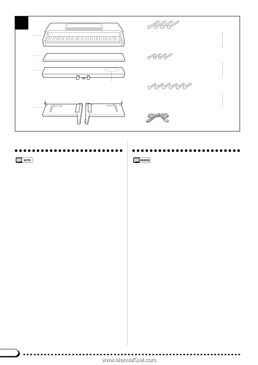
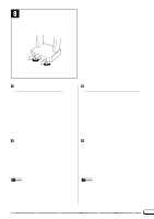
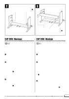
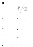
1 A B C D Bundled pedal cord inside Gebündeltes Pedalkabel Cordon de pédalier enroulé à l'intérieur Cable de pedales enrollado en el interior 6 x 25 mm round-head screws x4 Rundkopfschrauben (6 x 25 mm) x 4 Vis à tête ronde de 6 x 25 mm x 4 1 Tornillos de cabeza redonda de 6 x 25 mm x 4 4 x 20 mm round-head screws x4 Rundkopfschrauben (4 x 20 mm) x 4 Vis à tête ronde de 4 x 20 mm x 4 2 Tornillos de cabeza redonda de 4 x 20 mm x 4 6 x 18 mm flat-head screws x6 Senkschrauben (6 x 18 mm) x 6 Vis à tête plate de 6 x 18 mm x 6 3 Tornillos de cabeza plana de 6 x 18 mm x 6 q AC power cord q Netzkabel q Cordon d'alimentation q Cable de alimentación de CA CVP-59S: Assembly CVP-59S: Zusammenbau • We do not recommend attempting to assemble the Clavinova alone. The job can be easily accomplished, however, with only two people. • Use only the screws provided or replacements of exactly the specified size. Using screws of the wrong size can result in damage to the instrument. ZOpen the box and remove all the parts. On opening the box you should find the parts shown in the illustration above. Check to make sure that all the required parts are provided. XAttach the side panels (D) to the pedal box (C). Before installing the pedal box, untie and straighten out the bundled cord attached to the bottom of the pedal box. Place the pedal box on top of the wooden blocks attached to the side panels (D), and attach using the four 6 x 25 mm round-head screws 1 - two screws on each side. Make sure the pedals extend in the same direction as the feet. CAttach the center panel (B) to the side panels (D). The center panel (B) should be screwed to the vertical brackets on the side panels (D) using the four 4 x 20 mm round-head screws 2, as shown in the illustration. Make sure the center panel is attached to the side of the brackets facing the pedals. 150 • Wir raten Ihnen davon ab, das Clavinova alleine zusammenzubauen und aufzustellen. Zwei Personen können diese Arbeit jedoch problemlos ausführen. • Verwenden Sie ausschließlich die mitgeliefenten Schrauben oder Ersatzschrauben identischer Größe. Die Verwendung von Schrauben mit abweichenden Maßen kann eine Beschädigung des Instruments zur Folge haben. ZDen Versandkarton öffnen und alle Teile auspacken. Der Karton sollte alle in der Abbildung gezeigten Teile enthalten. Vergewissern Sie sich, daß alle Teile vollzählig vorhanden sind. XDie Seitenwände (D) mit dem Pedalkasten (C) verschrauben. Bevor Sie den Pedalkasten festschrauben, lösen Sie zunächst das an der Unterseite des Pedalkastens befestigte Kabel und ziehen es gerade. Setzen Sie den Pedalkasten auf die Holzklötze an den Innenseiten der Seitenwände (D), um ihn dann mit den vier größeren Rundkopfschrauben (6 x 25 mm) 1 festzuschrauben (jeweils zwei Schrauben links und rechts). Achten Sie darauf, daß die Pedale und die Füße in dieselbe Richtung weisen. CDie Rückwand (B) an die beiden Seitenwände (D) schrauben. Die Rückwand wird an den beiden senkrecht angebrachten Halterungen mit den vier kleineren Rundkopfschrauben (4 x 20 mm) 2 festgeschraubt, wie in der Abbildung gezeigt. Achten Sie darauf, daß die Rückwand vor den Halterungen angesetzt und festgeschraubt wird.
-
 1
1 -
2
-
3
-
4
-
5
-
6
-
7
-
8
-
9
-
10
-
11
-
12
-
13
-
14
-
15
-
16
-
17
-
18
-
19
-
20
-
21
-
22
-
23
-
24
-
25
-
26
-
27
-
28
-
29
-
30
-
31
-
32
-
33
-
34
-
35
-
36
-
37
-
38
-
39
-
40
-
41
-
42
-
43
-
44
-
45
-
46
-
47
-
48
-
49
-
50
-
51
-
52
-
53
-
54
-
55
-
56
-
57
-
58
-
59
-
60
-
61
-
62
-
63
-
64
-
65
-
66
-
67
-
68
-
69
-
70
-
71
-
72
-
73
-
74
-
75
-
76
-
77
-
78
-
79
-
80
-
81
-
82
-
83
-
84
-
85
-
86
-
87
-
88
-
89
-
90
-
91
-
92
-
93
-
94
-
95
-
96
-
97
-
98
-
99
-
100
-
101
-
102
-
103
-
104
-
105
-
106
-
107
-
108
-
109
-
110
-
111
-
112
-
113
-
114
-
115
-
116
-
117
-
118
-
119
-
120
-
121
-
122
-
123
-
124
-
125
-
126
-
127
-
128
-
129
-
130
-
131
-
132
-
133
-
134
-
135
-
136
-
137
-
138
-
139
-
140
-
141
-
142
-
143
-
144
-
145
-
146
-
147
-
 148
148 -
 149
149 -
 150
150 -
 151
151 -
 152
152 -
 153
153 -
 154
154 -
 155
155 -
 156
156 -
 157
157 -
 158
158 -
159
-
160
-
161
-
162
-
163
 |
 |