Yamaha DTX432K DTX402K/DTX432K/DTX452K Owners Manual - Page 20
Setup, For DTX432K and DTX452K, Assembling the kick pad
 |
View all Yamaha DTX432K manuals
Add to My Manuals
Save this manual to your list of manuals |
Page 20 highlights
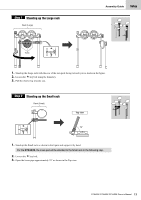
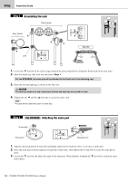
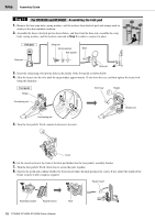
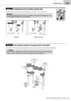
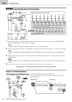
Setup Assembly Guide Step 11 For DTX432K and DTX452K Assembling the kick pad 1. Remove the four wing bolts, spring washers, and flat washers from the kick pad, and arrange each set nearby in the disassembled condition. 2. Assemble the base to the kick pad as shown below, and then from the base side, assemble the wing bolts, spring washers, and flat washers removed in Step 1 in order to secure it in place. Kick pad Wing bolt Spring washer Flat washer Base Kick pad Kick pad 3. Insert the connecting rods into the holes in the holder of the foot pedal as shown below. 4. Slide the beater into the hole until the tip protrudes approximately 15 mm from the rear, and then tighten the beater bolt using the drum key. Foot pedal Holder Drum key Beater Connecting rod Beater bolt Connecting rod 5. Turn the foot pedal's T-bolt counter-clockwise to loosen it. T-bolt 6. Fit the raised section at the front of the kick pad holder into the foot-pedal's assembly bracket. 7. Turn the foot pedal's T-bolt clock wise to secure the parts together. 8. Operate the pedal and confirm whether the beater head strikes the kick pad near the center. If not, adjust the length of the beater or move it left or right as required. Beater head Assembly bracket Raised section T-bolt 18 DTX402K DTX432K DTX452K Owner's Manual
-
 1
1 -
2
-
3
-
4
-
5
-
6
-
7
-
8
-
9
-
10
-
11
-
12
-
13
-
14
-
 15
15 -
 16
16 -
 17
17 -
 18
18 -
 19
19 -
 20
20 -
 21
21 -
 22
22 -
 23
23 -
 24
24 -
 25
25 -
26
-
27
-
28
-
29
-
30
-
31
-
32
-
33
-
34
-
35
-
36
-
37
-
38
-
39
-
40
-
41
-
42
-
43
-
44
-
45
-
46
-
47
-
48
-
49
-
50
-
51
-
52
-
53
-
54
-
55
-
56
-
57
-
58
-
59
-
60
-
61
-
62
-
63
-
64
-
65
-
66
-
67
-
68
-
69
-
70
-
71
-
72
 |
 |
