Yamaha DTXPLORER Owner's Manual - Page 25
TRIG2, ¡snare, TP1/SnrA, Completed, Medium, TRIG2*¡snare - tp65s
 |
View all Yamaha DTXPLORER manuals
Add to My Manuals
Save this manual to your list of manuals |
Page 25 highlights
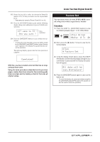
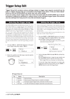
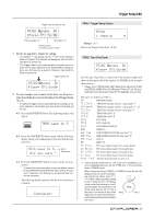
Trigger Setup Edit Trigger Input you want to edit TRIG2 ¡snare 0% -Type= TP1/SnrA, Previous page icon Next page icon Flashing cursor (the item you want to edit) 3. Rotate the jog dial to change the setting. * An asterisk "*" will appear next to "TRIG" in the display if data is changed. This asterisk will disappear after the store operation is carried out. * The Trigger Input Level produced when the pads are hit is given on the upper right side in the display. When setting the gain, use this level as a guide to measure how hard the pads are being hit. Trigger Input Level TRIG2*¡snare 0% -Type= TP1/SnrB, 4. To save changes you've made to the data, use the procedure described below to store the data in User Trigger Setup (No. 5). * If a different trigger setup is selected before carrying out the store operation, all changes you have made to the data will be lost. 4-1. Press the [SAVE/ENT] button. The following display will appear. TRIG save to 5 4-2. Press the [SAVE/ENT] button again and the following display asking your confirmation to proceed with the store operation. TRIG save to 5 Are you sure ? Store Destination 4-3. Press the [SAVE/ENT] button to carry out the store operation. * To cancel the store operation, press any button except for the [SAVE/ENT] and [SHIFT] buttons (when "Are you sure?" appears in the display, the jog dial will also cancel the operation). The following display appears after the store operation is complete. Completed! TRIG1 Trigger Setup Select TRIG1 1 :Medium , [Range] 1 to 5 Selects the Trigger Setup Type. (P. 24) TRIG2 Type (Pad Type) TRIG2 ¡snare 0% -Type= TP1/SnrA, Sets the type of pad that is connected to the assigned input jack shown in the upper half of the display ([1 SNARE] in the example shown above). * Values set in [TRIG3 Gain, MVl (Mininimum Velocity)] (P. 26) and [TRIG5 SelfRejTime (Self Rejection Time)] (P. 26) will automatically select the proper value for the pad type you set here. Pad types are defined as follows. KP KP80S/80/65/60 TP1/SnrA TP65S/65 (mainly used as a snare pad) *1 TP1/SnrB TP65S/65 (mainly used as a snare pad) *1, *2 TP1/Tom TP65S/65 (mainly used as a tom pad) *1 TP2-A TP80S/80/65/60 *3 TP2-B TP80S/80/65/60 *3 PCY1 PCY150S PCY2 PCY130S/130 PCY3 PCY80S/80/65/60/10 RHH RHH130 RHP Pad RHP120SD/120/100/80 (pad side) *4 RHP Rim RHP120SD/120/100/80 (rim side) *4 RHP Kick KP120 BP BP80 *5 DT Snare DT series drum trigger (for a snare drum) DT HiTom DT series drum trigger (for small toms) DT LoTom DT series drum trigger (for large toms) DT Kick DT series drum trigger (for bass drum) misc 1 to 6 Another manufacturer's pad 1 to 6. *1 3-zone function (pad voice x1, rim voice x2) is available to a 3zone compatible pad such as the TP65S, etc., if it is connected to the 1 SNARE input. When connected to the 5 RIDE or 6 CRASH jacks, the rim will produce only one voice. For produc- ing closed rim shots, the [TP1/ SnrA] has a high sensitivity setting on rim 1, while the [TP1/SnrB] has a high sensitivity setting on rim 2. Left and right rim sensitivity is set at the same level for [TP1/Tom]. If the pad is connected to any other Rim 2 Rim 1 input, the rim voice will not be pro- duced and the pad will only produce one voice. 25
-
 1
1 -
2
-
3
-
4
-
5
-
6
-
7
-
8
-
9
-
10
-
11
-
12
-
13
-
14
-
15
-
16
-
17
-
18
-
19
-
 20
20 -
 21
21 -
 22
22 -
 23
23 -
 24
24 -
 25
25 -
 26
26 -
 27
27 -
 28
28 -
 29
29 -
 30
30 -
31
-
32
-
33
-
34
-
35
-
36
 |
 |
