Yamaha IMX644 Owner's Manual - Page 13
Connectors and Cables, MONO INPUT] and [OUTPUT] Con, nectors 3-pin Euroblock
 |
View all Yamaha IMX644 manuals
Add to My Manuals
Save this manual to your list of manuals |
Page 13 highlights
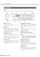
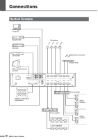
Connections Connectors and Cables ■ [MONO INPUT] and [OUTPUT] Connectors (3-pin Euroblock) Connect external microphones, amplifiers and other devices to the rear-panel [MONO INPUT] and [OUTPUT] connectors via cables fitted with the supplied 3-pin Euroblock plugs. Follow the procedure outlined in this section to attach the Euroblock plugs to the appropriate cables. Euroblock Pin Assignments 123 Pin No. 1 2 3 Signal name HOT COLD GND Use balanced lines to connect microphones and similar sources to the [MONO INPUT] connectors. Wire balanced cables as shown in the diagram below. XLR-3-11C (or equivalent) 1 3 2 2 1 3 When an amplifier to be connected to the OUTPUT connector has balanced XLR type inputs, wire the connection cable as shown in the diagram below. XLR-3-12C (or equivalent) Euroblock Plug Connection NOTE • A "minus" type screwdriver with a blade width of approximately 3 millimeters is recommended for Euroblock connector attachment. 3mm 1 Strip the insulation from cables to be attached to a Euroblock plug as shown below. Shielded cable 7mm 30mm CAUTION • Be sure to use shielded cables. • Do not tin (plate with solder) the exposed sections of the cable. 2 Loosen the terminal screws. Terminal screw Loosen Slotted screwdriver Euroblock plug 3 Insert the cables. 1 3 2 1 2 3 4 Securely tighten the terminal screws. Pull the cables (not too strongly) to confirm that they are securely connected. 5 Connect the Euroblock plug to the IMX644 Euroblock connector. IMX644 Owner's Manual 13
-
 1
1 -
2
-
3
-
4
-
5
-
6
-
7
-
 8
8 -
 9
9 -
 10
10 -
 11
11 -
 12
12 -
 13
13 -
 14
14 -
 15
15 -
 16
16 -
 17
17 -
 18
18 -
19
-
20
-
21
-
22
-
23
-
24
-
25
-
26
-
27
-
28
 |
 |
