Yamaha MG82CX Owner's Manual - Page 11
Master Control Equalizer HIGH, MID, and LOW, EFFECT AUX Control, PAN Control CHs 1 - stereo mixer with effects
 |
UPC - 086792859347
View all Yamaha MG82CX manuals
Add to My Manuals
Save this manual to your list of manuals |
Page 11 highlights
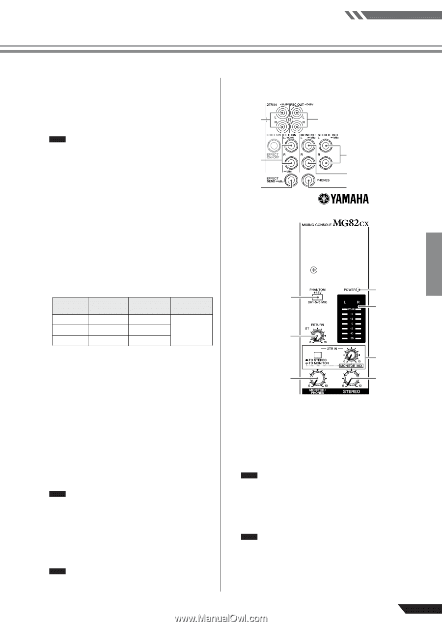
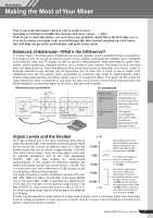
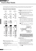
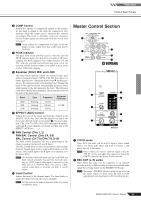
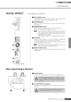
Reference Front & Rear Panels 8 COMP Control Adjusts the amount of compression applied to the channel. As the knob is turned to the right the compression ratio increases while the output gain is automatically adjusted accordingly. The result is smoother, more even dynamics because louder signals are attenuated while the overall level is boosted. NOTE Avoid setting the compression too high, as the the higher average output level that results may lead to feedback. 9 PEAK Indicator The peak level of the post-EQ signal is detected, and the PEAK indicator lights red when the level reaches 3 dB below clipping. For XLR-equipped stereo input channels (3/4 and 5/6), both the post-EQ and post-mic-amp peak levels are detected, and the indicator lights red if either of these levels reaches 3 dB below clipping. 0 Equalizer (HIGH, MID, and LOW) This three-band equalizer adjusts the channel's high, mid, and low frequency bands. CH 7/8 (CHs 7/8, 9/10) have two bands: high and low. Setting the knob to the t position produces a flat response in the corresponding band. Turning the knob to the right boosts the corresponding frequency band, while turning to the left attenuates the band. The following table shows the EQ type, frequency, and maximum cut/boost for each of the three bands. Band Type Frequency Maximum Cut/Boost HIGH Shelving 10 kHz MID Peaking 2.5 kHz ±15 dB LOW Shelving 100 Hz A EFFECT (AUX) Control Adjusts the level of the signal sent from the channel to the EFFECT (AUX) bus. Note that the signal level sent to the bus is also affected by the Level control C. On stereo channels (CHs 3/4 to 7/8 (CHs 3/4 to 9/10)) the signals from the L (odd) and R (even) channels are mixed and then sent to the EFFECT (AUX) bus. B PAN Control (CHs 1, 2) PAN/BAL Control (CHs 3/4, 5/6) BAL Control (CH 7/8 (CHs 7/8, 9/10) The PAN control determines the stereo positioning of the channel signal on the Stereo L and R buses. The BAL control knob sets the balance between left and right channels. Signals input to the L input (odd channel) go to the Stereo L bus; signals input to the R input (even channel) go to the Stereo R bus. NOTE On channels where this knob provides both PAN and BAL control (channels 3/4 and 5/6), the knob operates as a PAN control when input is received via the MIC jack or L (MONO) input only, and as a BAL control when input is received via both L and R inputs. C Level Control Adjusts the level of the channel signal. Use these knobs to adjust the balance between the various channels. NOTE Set the controls for unused channels all the way down to minimize noise. Master Control Section 1 2 5 3 6 4 7 0 8 A 9 B C D MG82CX 1 2TR IN Jacks These RCA pin jacks can be used to input a stereo sound source. Use these jacks when you want to connect a CD player directly to the mixer. NOTE Select where you want to send the signal using the 2TR IN switch, and adjust the signal level using the 2TR IN control in the Master Control section. 2 REC OUT (L, R) Jacks These RCA pin jacks can be connected to an external recorder such as an MD recorder in order to record the same signal that is being output via the STEREO OUT jacks. NOTE The mixer's STEREO Master control has no affect on the signal output via these jacks. Be sure to make appropriate level adjustments at the recording device. MG82CX/MG102C Owner's Manual 11
-
 1
1 -
2
-
3
-
4
-
5
-
 6
6 -
 7
7 -
 8
8 -
 9
9 -
 10
10 -
 11
11 -
 12
12 -
 13
13 -
 14
14 -
 15
15 -
 16
16 -
17
-
18
-
19
-
20
-
21
 |
 |