Yamaha MG82CX Owner's Manual - Page 12
Return L Mono, R Jacks, Send Effect Aux Jack, Stereo Out L, Monitor L, Phones Jack - 8 channel mixer with effects
 |
UPC - 086792859347
View all Yamaha MG82CX manuals
Add to My Manuals
Save this manual to your list of manuals |
Page 12 highlights
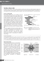
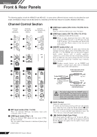
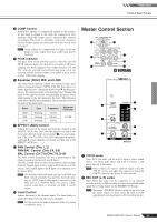
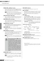
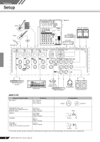
Reference Front & Rear Panels 3 RETURN L (MONO), R Jacks These are unbalanced phone-jack type line inputs. The signal received by these jacks is sent to the STEREO L/R buses. These jacks are typically used to receive the signal returned from an external effect device (reverb, delay, etc.). NOTE These jacks can also be used as an auxiliary stereo input. If you connect to the L (MONO) jack only, the mixer will recognize the signal as monaural and will send the identical signal to both the L and R jacks. 4 SEND EFFECT (AUX) Jack This is an impedance balanced* phone-jack type output that outputs the signal from the EFFECT (AUX) bus. You can use this jack, for example, to connect to an external effect unit. 5 STEREO OUT (L, R) Jacks These are impedance balanced* phone-jack type outputs that output the signals adjusted by the STEREO Master control. You can use these jacks, for example, to connect to the power amplifier driving your main speakers. 6 MONITOR (L, R) Jacks These are impedance balanced* phone-jack type outputs that output the signals adjusted by the MONITOR/PHONES control. Connect these jacks to your monitor system. 7 PHONES Jack Connect a pair of headphones to this stereo phone jack. The PHONES jack outputs the same signal as the MONITOR OUT jacks. 8 PHANTOM +48 V Switch This switch toggles phantom power on and off. When the switch is on the mixer supplies +48V phantom power to all channels that have XLR mic input jacks (CHs 1-5/6). Turn this switch on when using one or more phantom-powered condenser microphones. NOTE When this switch is on the mixer supplies DC +48 V power to pins 2 and 3 of all XLR-type MIC INPUT jacks. • Be sure to leave this switch off ( ) if you do not need phantom power. CAUTION • When tuning the switch on ( ), be sure that only condenser mics are connected to the XLR input jacks (CHs: 1 to 5/6). Devices other than condenser mics may be damaged if connected to the phantom power supply. Note, however, that the switch may be left on when connecting to balanced dynamic microphones. • To avoid damage to speakers, be sure to turn off amplifiers (or powered speakers) before turning this switch on or off. We also recommend that you turn all output controls (STEREO Master control, etc.) to their minimum settings before operating the switch to avoid the risk of loud noises that could cause hearing loss or device damage. 9 RETURN Control Adjusts the level at which the signal received at the RETURN jacks (L (MONO) and R) is sent to the STEREO L/R bus. NOTE If you supply a signal to the RETURN L (MONO) jack only, the mixer sends the same signal to both the L and R Stereo buses. 0 POWER Indicator This indicator lights when the mixer's power is ON. A Level Meter This LED meter displays the level of the signal sent to the MONITOR jacks and the PHONES jack. The "0" segment corresponds to the nominal output level. The PEAK segment lights red when the output reaches the clipping level. B 2TR IN • 2TR IN Switch If it is set to TO STEREO ( ), the signals are sent to the STEREO L/R buses. If this switch is set to TO MONITOR ( ), the signals input via the 2TR IN jacks are sent to the MONITOR OUT jacks, the PHONES jack, and the level meter. The MONITOR MIX feature becomes available when it is set to TO MONITOR ( ). * : When overdubbing, you can adjust the levels of the monitor playback signal and the signal being recorded separately. MONITOR MIX Signal Flow 2TR IN 2TR IN Control Playback signal Recording signal MONITOR/PHONES Controls STEREO buses MONITOR/ PHONES jacks STEREO Master Control REC OUT • 2TR IN control Adjusts the level of the signal sent from the 2TR IN jacks to the STEREO L/R buses. C MONITOR/PHONES Control Controls the level of the signal output to the PHONES jack and the MONITOR jacks. D STEREO Master Control Adjusts the signal level sent to the STEREO OUT jacks. * Impedance Balanced Since the hot and cold terminals of impedance balanced output jacks have the same impedance, these outputs are less affected by induced noise. 12 MG82CX/MG102C Owner's Manual
-
 1
1 -
2
-
3
-
4
-
5
-
6
-
 7
7 -
 8
8 -
 9
9 -
 10
10 -
 11
11 -
 12
12 -
 13
13 -
 14
14 -
 15
15 -
 16
16 -
 17
17 -
18
-
19
-
20
-
21
 |
 |