Yamaha R-S201 Owners Manual - Page 14
REC jacks, Connecting speaker cables, Bi-wire connection, CAUTION
 |
View all Yamaha R-S201 manuals
Add to My Manuals
Save this manual to your list of manuals |
Page 14 highlights
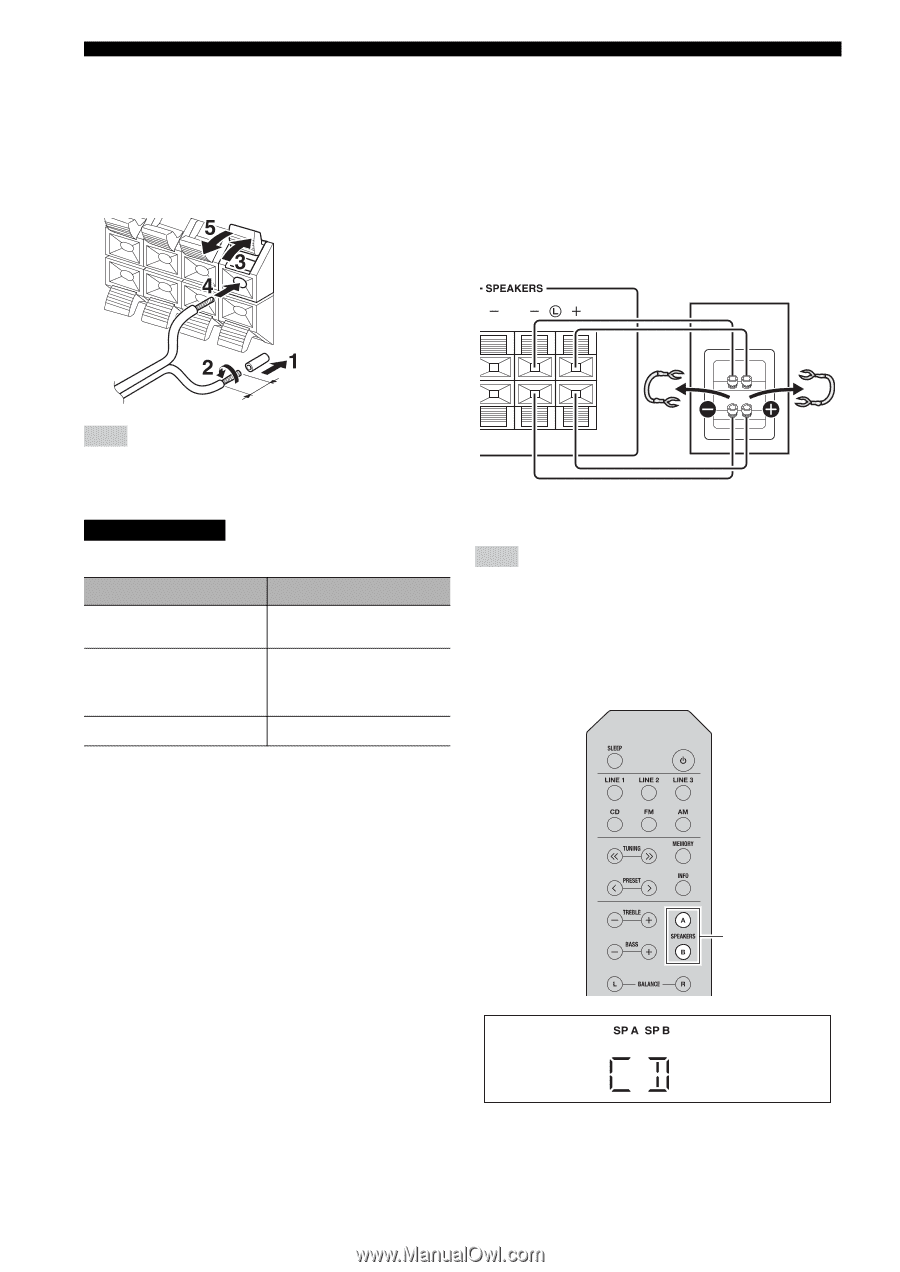
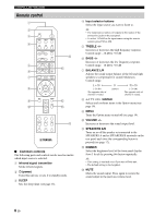
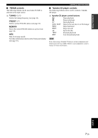
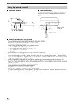
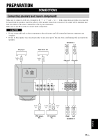
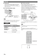
CONNECTIONS ■ REC jacks • The REC jacks output audio signals of the currently selected input (except when LINE 3 is selected). • Volume level, tone control and balance settings do not affect the REC jacks. ■ Connecting speaker cables ■ Bi-wire connection Bi-wire connection separates the woofer from the combined midrange and tweeter section. A bi-wire compatible speaker has four binding post terminals. These two sets of terminals allow the speaker to be split into two independent sections. With these connections, the mid and high frequency drivers are connected to one set of terminals and the low frequency driver to another set of terminals. Rear panel Speaker Remove approximately 10 mm (3/8 in) of insulation from the end of each speaker cable. Note When inserting speaker cables into the speaker terminals, insert only the bare speaker wire. If insulated cable is inserted, the connection may be poor and sound may not be heard. CAUTION Speaker impedance must be set as shown below. Speaker connection SPEAKERS A or SPEAKERS B SPEAKERS A and SPEAKERS B Bi-wiring Speaker impedance 8 Ω or higher 16 Ω or higher (except for North America model) 8 Ω or higher Connect the other speaker to the other set of terminals in the same way. Note When making bi-wire connections, remove the shorting bridges or cables on the speaker. y To use the bi-wire connections, press SPEAKERS A and SPEAKERS B so that both SP A and B light up on the front panel display. SPEAKERS A/B 10 En
-
 1
1 -
2
-
3
-
4
-
5
-
6
-
7
-
8
-
 9
9 -
 10
10 -
 11
11 -
 12
12 -
 13
13 -
 14
14 -
 15
15 -
 16
16 -
 17
17 -
 18
18 -
 19
19 -
20
-
21
-
22
-
23
-
24
-
25
-
26
-
27
-
28
 |
 |