Yamaha YMC10 YMC10 Owners Manual Image - Page 7
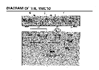
Power, Switch, Indicator, Connectors, Select, Jacks
 |
View all Yamaha YMC10 manuals
Add to My Manuals
Save this manual to your list of manuals |
Page 7 highlights
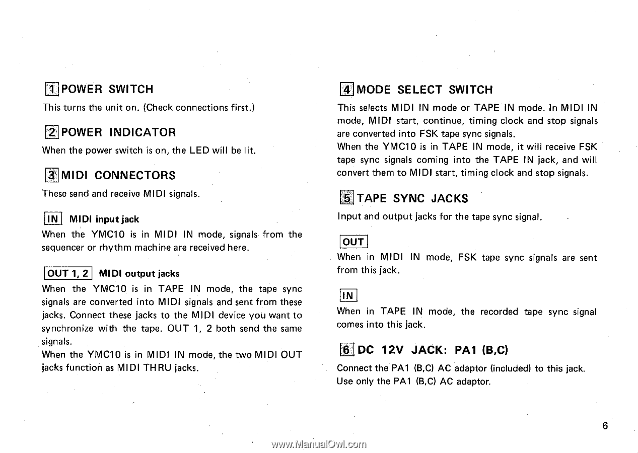
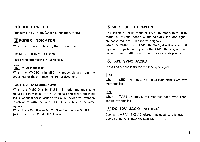
I11POWER SWITCH This turns the unit on. (Check connections first.) 2 POWER INDICATOR When the power switch is on, the LED will be lit. 3 MIDI CONNECTORS These send and receive MIDI signals. IN MIDI input jack When the YMC10 is in MIDI IN mode, signals from the sequencer or rhythm machine are received here. OUT 1, 2 MIDI output jacks When the YMC10 is in TAPE IN mode, the tape sync signals are converted into MIDI signals and sent from these jacks. Connect these jacks to the MIDI device you want to synchronize with the tape. OUT 1, 2 both send the same signals. When the YMC10 is in MIDI IN mode, the two MIDI OUT jacks function as MIDI THRU jacks. 141MODE SELECT SWITCH This selects MIDI IN mode or TAPE IN mode. In MIDI IN mode, MIDI start, continue, timing clock and stop signals are converted into FSK tape sync signals. When the YMC10 is in TAPE IN mode, it will receive FSK tape sync signals coming into the TAPE IN jack, and will convert them to MIDI start, timing clock and stop signals. 5 TAPE SYNC JACKS Input and output jacks for the tape sync signal. OUT When in MIDI IN mode, FSK tape sync signals are sent from this jack. IN When in TAPE IN mode, the recorded tape sync signal comes into this jack. 6 DC 12V JACK: PA1 (B,C) Connect the PA1 (B,C) AC adaptor (included) to this jack. Use only the PA1 (B,C) AC adaptor. 6
-
 1
1 -
 2
2 -
 3
3 -
 4
4 -
 5
5 -
 6
6 -
 7
7 -
 8
8 -
 9
9 -
 10
10 -
 11
11 -
 12
12 -
13
-
14
-
15
-
16
-
17
-
18
-
19
 |
 |