ZyXEL ES-1024B User Guide - Page 21
Hardware Installation
 |
View all ZyXEL ES-1024B manuals
Add to My Manuals
Save this manual to your list of manuals |
Page 21 highlights
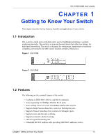
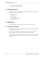
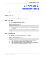
ES-1016B/1024B User's Guide 2.2.2 Front Panel Connections You can use unshielded twisted pair (UTP) or shielded twisted-pair (STP) Ethernet cables for RJ-45 ports. The following table describes the types of network cable used for the different connection speeds. Note: Make sure the cable length between connections does not exceed 100 meters (328 feet). Table 1 Network Cable Types SPEED 10 Base-T 100 Base-TX NETWORK CABLE TYPE 100Ω 2-pair UTP/STP Category 3, 4 or 5 100Ω 2-pair UTP/STP Category 5 2.2.3 Front Panel LEDs The LED Indicators give real-time information about the status of the switch. The following table provides descriptions of the LEDs. Figure 6 Front Panel LEDs (ES-1024A) The following table describes the LEDs. Table 2 The Front Panel LED Descriptions LED PWR LINK/ ACT COLOR STATUS Green On Off Green On Blinking Off DESCRIPTION The switch is on and receiving power. The switch is not receiving power. The port is connected to an Ethernet network. The port is receiving or transmitting data. The port is not connected to an Ethernet network. 2.3 Hardware Installation Refer to the Quick Start Guide for hardware installation instructions. 18 Chapter 2 Hardware Description and Connection
-
 1
1 -
2
-
3
-
4
-
5
-
6
-
7
-
8
-
9
-
10
-
11
-
12
-
13
-
14
-
15
-
 16
16 -
 17
17 -
 18
18 -
 19
19 -
 20
20 -
 21
21 -
 22
22 -
 23
23 -
 24
24 -
 25
25 -
 26
26 -
27
-
28
 |
 |
