ZyXEL IES-5112 Series User Guide - Page 41
IES-6000M Card Connections
 |
View all ZyXEL IES-5112 Series manuals
Add to My Manuals
Save this manual to your list of manuals |
Page 41 highlights
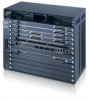
Chapter 2 Hardware Installation and Connections Note: Use 180-degree Telco-50 cables for VoIP rear panel connections (see Chapter 5 on page 75 for information on 180-degree Telco-50 cable length). Figure 33 DSL and VoIP Rear Panel Telco-50 Connections (2 Splitter Chassis) ASC1024 SEC1024 • Connect the USER Telco-50 connector from the extension card attached to the VoIP line card's 1 ~ 24 ports to the CO Telco-50 connector of the splitter card attached to the DSL line card's 1 ~ 24 ports. • Connect the USER Telco-50 connector from the extension card attached to the VoIP line card's 25 ~ 48 ports to the CO Telco-50 connector of the splitter card attached to the DSL line card's 25 ~ 48 ports. When you do not use the VoIP line card in conjunction with a DSL splitter card, connect the USER Telco-50 connectors to the subscribers' telephone wiring. In most multi-tenant unit applications, the USER pins connect to the subscribers' telephone wiring via a Main Distribution Frame (MDF). 2.5 IES-6000M Card Connections The following describes how to connect the line cards to the splitter chassis cards. For the management switch card, refer to the card's User's Guide for instructions on making the connections. Use a Telco-50 cable to connect the line card's front panel Telco-50 connector to the corresponding splitter or extension card's front panel Telco-50 connector. Make sure that you use the appropriate length Telco-50 cables with the line cards, as using cables of the wrong length blocks access to other cards. See Chapter 5 on page 75 for the lengths of ZyXEL's optional Telco-50 cables. Follow these directions if there is one splitter chassis below the IES-6000M main chassis. • Use a short Telco-50 cable to connect a line card's 25-48 Telco-50 connector to the Telco-50 connector on the corresponding splitter or extension card. • Use a long Telco-50 cable to connect a line card's 1-24 Telco-50 connector to the Telco-50 connector on the corresponding splitter or extension card. Follow these directions if there are two splitter chassis below the IES-6000M main chassis. IES-5106M / IES-5112M / IES-6000M User's Guide 41
-
 1
1 -
2
-
3
-
4
-
5
-
6
-
7
-
8
-
9
-
10
-
11
-
12
-
13
-
14
-
15
-
16
-
17
-
18
-
19
-
20
-
21
-
22
-
23
-
24
-
25
-
26
-
27
-
28
-
29
-
30
-
31
-
32
-
33
-
34
-
35
-
 36
36 -
 37
37 -
 38
38 -
 39
39 -
 40
40 -
 41
41 -
 42
42 -
 43
43 -
 44
44 -
 45
45 -
 46
46 -
47
-
48
-
49
-
50
-
51
-
52
-
53
-
54
-
55
-
56
-
57
-
58
-
59
-
60
-
61
-
62
-
63
-
64
-
65
-
66
-
67
-
68
-
69
-
70
-
71
-
72
-
73
-
74
-
75
-
76
-
77
-
78
-
79
-
80
-
81
-
82
-
83
-
84
-
85
-
86
-
87
-
88
 |
 |
