ZyXEL MGS-3712 User Guide - Page 89
Basic Setting > IP Setup, continued
 |
View all ZyXEL MGS-3712 manuals
Add to My Manuals
Save this manual to your list of manuals |
Page 89 highlights
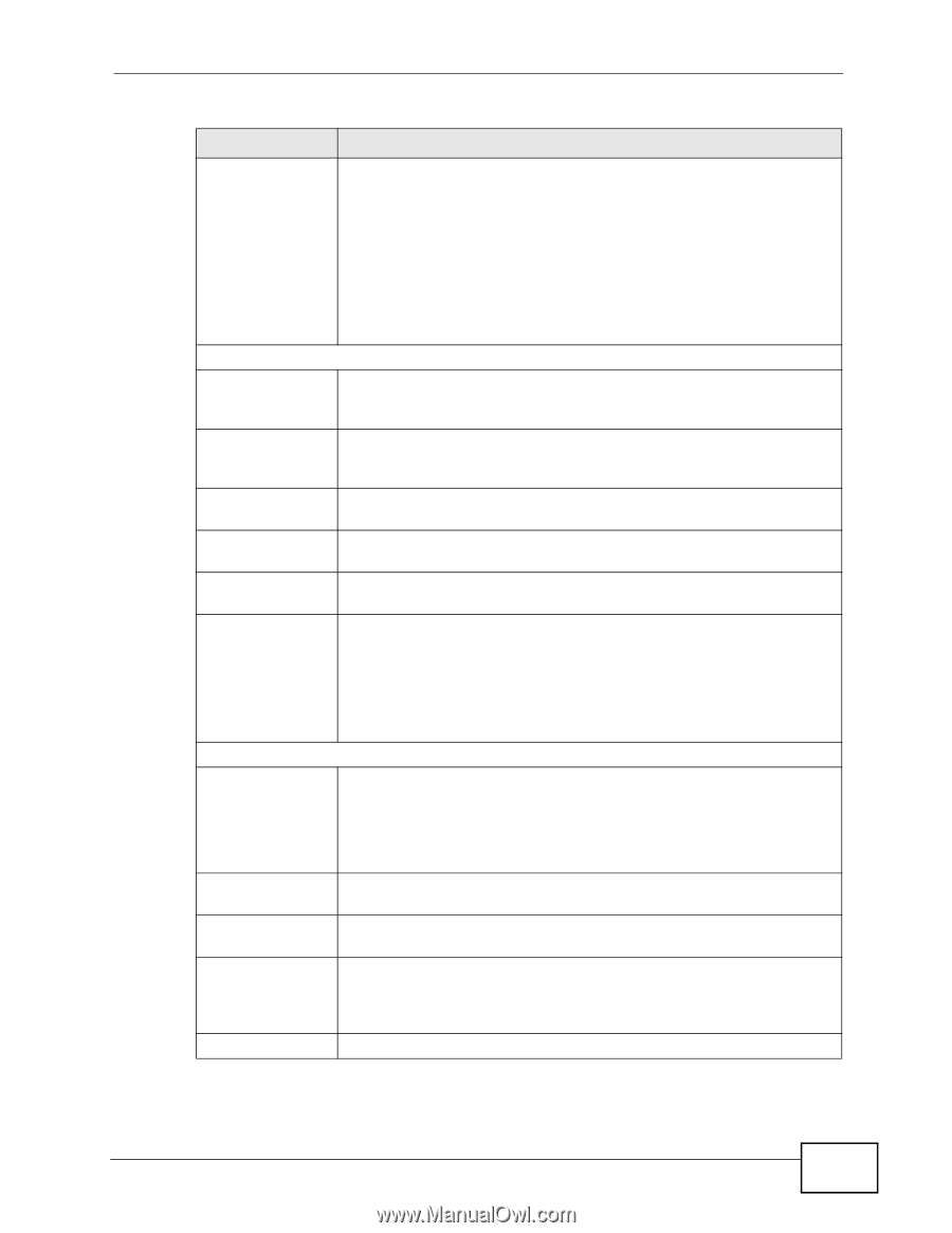
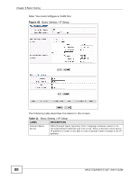
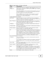
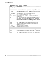
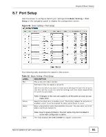
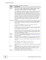
Chapter 8 Basic Setting Table 11 Basic Setting > IP Setup (continued) LABEL DESCRIPTION Default Management Specify which traffic flow (In-Band or Out-of-band) the Switch is to send packets originating from itself (such as SNMP traps) or packets with unknown source. Select Out-of-band to have the Switch send the packets to the outof-band management port. This means that device(s) connected to the other port(s) do not receive these packets. Select In-Band to have the Switch send the packets to all ports except the out-of-band management port to which connected device(s) do not receive these packets. In-Band Management IP Address DHCP Client Select this option if you have a DHCP server that can assign the Switch an IP address, subnet mask, a default gateway IP address and a domain name server IP address automatically. Static IP Address Select this option if you don't have a DHCP server or if you wish to assign static IP address information to the Switch. You need to fill in the following fields when you select this option. IP Address Enter the IP address of your Switch in dotted decimal notation for example 192.168.1.1. IP Subnet Mask Enter the IP subnet mask of your Switch in dotted decimal notation for example 255.255.255.0. Default Gateway Enter the IP address of the default outgoing gateway in dotted decimal notation, for example 192.168.1.254. VID Enter the VLAN identification number associated with the Switch IP address. This is the VLAN ID of the CPU and is used for management only. The default is "1". All ports, by default, are fixed members of this "management VLAN" in order to manage the device from any port. If a port is not a member of this VLAN, then users on that port cannot access the device. To access the Switch make sure the port that you are connected to is a member of Management VLAN. Out-of-band Management IP Address IP Address Enter the IP address of your Switch in dotted decimal notation for example 192.168.0.1. Subnet Mask Default Gateway Apply Cancel If you change this IP address, make sure the computer connected to this management port is in the same subnet before accessing the Switch. Enter the IP subnet mask of your Switch in dotted decimal notation for example 255.255.255.0. Enter the IP address of the default outgoing gateway in dotted decimal notation, for example 192.168.0.254. Click Apply to save your changes to the Switch's run-time memory. The Switch loses these changes if it is turned off or loses power, so use the Save link on the top navigation panel to save your changes to the non-volatile memory when you are done configuring. Click Cancel to begin configuring the fields again. MGS-3712/MGS-3712F User's Guide 89
-
 1
1 -
2
-
3
-
4
-
5
-
6
-
7
-
8
-
9
-
10
-
11
-
12
-
13
-
14
-
15
-
16
-
17
-
18
-
19
-
20
-
21
-
22
-
23
-
24
-
25
-
26
-
27
-
28
-
29
-
30
-
31
-
32
-
33
-
34
-
35
-
36
-
37
-
38
-
39
-
40
-
41
-
42
-
43
-
44
-
45
-
46
-
47
-
48
-
49
-
50
-
51
-
52
-
53
-
54
-
55
-
56
-
57
-
58
-
59
-
60
-
61
-
62
-
63
-
64
-
65
-
66
-
67
-
68
-
69
-
70
-
71
-
72
-
73
-
74
-
75
-
76
-
77
-
78
-
79
-
80
-
81
-
82
-
83
-
 84
84 -
 85
85 -
 86
86 -
 87
87 -
 88
88 -
 89
89 -
 90
90 -
 91
91 -
 92
92 -
 93
93 -
 94
94 -
95
-
96
-
97
-
98
-
99
-
100
-
101
-
102
-
103
-
104
-
105
-
106
-
107
-
108
-
109
-
110
-
111
-
112
-
113
-
114
-
115
-
116
-
117
-
118
-
119
-
120
-
121
-
122
-
123
-
124
-
125
-
126
-
127
-
128
-
129
-
130
-
131
-
132
-
133
-
134
-
135
-
136
-
137
-
138
-
139
-
140
-
141
-
142
-
143
-
144
-
145
-
146
-
147
-
148
-
149
-
150
-
151
-
152
-
153
-
154
-
155
-
156
-
157
-
158
-
159
-
160
-
161
-
162
-
163
-
164
-
165
-
166
-
167
-
168
-
169
-
170
-
171
-
172
-
173
-
174
-
175
-
176
-
177
-
178
-
179
-
180
-
181
-
182
-
183
-
184
-
185
-
186
-
187
-
188
-
189
-
190
-
191
-
192
-
193
-
194
-
195
-
196
-
197
-
198
-
199
-
200
-
201
-
202
-
203
-
204
-
205
-
206
-
207
-
208
-
209
-
210
-
211
-
212
-
213
-
214
-
215
-
216
-
217
-
218
-
219
-
220
-
221
-
222
-
223
-
224
-
225
-
226
-
227
-
228
-
229
-
230
-
231
-
232
-
233
-
234
-
235
-
236
-
237
-
238
-
239
-
240
-
241
-
242
-
243
-
244
-
245
-
246
-
247
-
248
-
249
-
250
-
251
-
252
-
253
-
254
-
255
-
256
-
257
-
258
-
259
-
260
-
261
-
262
-
263
-
264
-
265
-
266
-
267
-
268
-
269
-
270
-
271
-
272
-
273
-
274
-
275
-
276
-
277
-
278
-
279
-
280
-
281
-
282
-
283
-
284
-
285
-
286
-
287
-
288
-
289
-
290
-
291
-
292
-
293
-
294
-
295
-
296
-
297
-
298
-
299
-
300
-
301
-
302
-
303
-
304
-
305
-
306
-
307
-
308
-
309
-
310
-
311
-
312
-
313
-
314
-
315
-
316
-
317
-
318
-
319
-
320
-
321
-
322
-
323
-
324
-
325
-
326
-
327
-
328
-
329
-
330
-
331
-
332
-
333
-
334
-
335
-
336
-
337
-
338
-
339
-
340
-
341
-
342
-
343
-
344
-
345
-
346
-
347
-
348
-
349
-
350
-
351
-
352
-
353
-
354
-
355
-
356
-
357
-
358
-
359
-
360
-
361
-
362
-
363
-
364
-
365
-
366
-
367
-
368
-
369
-
370
-
371
-
372
-
373
-
374
-
375
-
376
-
377
-
378
-
379
-
380
-
381
-
382
 |
 |