eMachines E181H Service Guide - Page 43
Connector Information
 |
View all eMachines E181H manuals
Add to My Manuals
Save this manual to your list of manuals |
Page 43 highlights
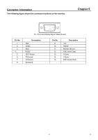
Connector Information The following figure shows the connector locations on the monitor: Chapter 5 Pin No. 1. 2. 3. 4. 5. 6. 7. 8. 1 5 6 10 11 15 15 - Pin Color Display Signal Cable (D-sub) Description Red Green Blue RS232 DDC-Return R-Ground G-Ground B-Ground Pin No. 9. 10. 11. 12. 13. 14. 15. Description +5V RS232 Monitor Ground DDC-Serial Data H-Sync V-Sync DDC-Serial Clock 43 43
-
 1
1 -
2
-
3
-
4
-
5
-
6
-
7
-
8
-
9
-
10
-
11
-
12
-
13
-
14
-
15
-
16
-
17
-
18
-
19
-
20
-
21
-
22
-
23
-
24
-
25
-
26
-
27
-
28
-
29
-
30
-
31
-
32
-
33
-
34
-
35
-
36
-
37
-
 38
38 -
 39
39 -
 40
40 -
 41
41 -
 42
42 -
 43
43 -
 44
44 -
 45
45 -
 46
46 -
 47
47 -
 48
48 -
49
-
50
-
51
-
52
-
53
-
54
-
55
-
56
-
57
-
58
-
59
-
60
-
61
 |
 |

43
43
Connector Information
The following figure shows the connector locations on the monitor:
1
5
6
10
11
15
15 – Pin Color Display Signal Cable (D-sub)
Pin No.
Description
Pin No.
Description
1.
Red
9.
+5V
2.
Green
10.
RS232
3.
Blue
11.
Monitor Ground
4.
RS232
12.
DDC-Serial Data
5.
DDC-Return
13.
H-Sync
6.
R-Ground
14.
V-Sync
7.
G-Ground
15.
DDC-Serial Clock
8.
B-Ground
Chapter 5