eMachines E181H Service Guide - Page 6
Table Of Contents - monitor troubleshoot
 |
View all eMachines E181H manuals
Add to My Manuals
Save this manual to your list of manuals |
Page 6 highlights
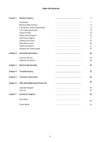
Table Of Contents Chapter 1 Monitor Features Introduction Electrical Requirements LCD Monitor General Specification LCD Panel Specification Support Timing Monitor Block Diagram Main Board Diagram Software Flow chart Main Board Layout Cable Connections Adjusting the viewing angle Chapter 2 Operating Instructions External Controls Adjusting the picture Chapter 3 Machine Disassembly Chapter 4 Troubleshooting Chapter 5 Connector Information Chapter 6 FRU (Field Replacement Unit) List Exploded Diagram Part List Chapter 7 Schematic Diagram Main Board Power Board 7 7 8 9 10 14 16 17 18 20 21 23 24 24 25 29 33 43 44 45 47 49 49 53 6
-
 1
1 -
 2
2 -
 3
3 -
 4
4 -
 5
5 -
 6
6 -
 7
7 -
 8
8 -
 9
9 -
 10
10 -
 11
11 -
 12
12 -
13
-
14
-
15
-
16
-
17
-
18
-
19
-
20
-
21
-
22
-
23
-
24
-
25
-
26
-
27
-
28
-
29
-
30
-
31
-
32
-
33
-
34
-
35
-
36
-
37
-
38
-
39
-
40
-
41
-
42
-
43
-
44
-
45
-
46
-
47
-
48
-
49
-
50
-
51
-
52
-
53
-
54
-
55
-
56
-
57
-
58
-
59
-
60
-
61
 |
 |

6
Table Of Contents
Chapter 1
Monitor Features
…………………………………………
7
Introduction
………………………………………
7
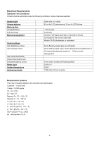
Electrical Requirements
………………………………………
8
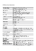
LCD Monitor General Specification
………………………………………
9
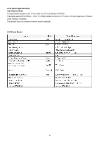
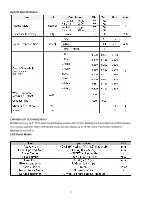
LCD Panel Specification
………………………………………
10
Support Timing
………………………………………
14
Monitor Block Diagram
………………………………………
16
Main Board Diagram
………………………………………
17
Software Flow chart
………………………………………
18
Main Board Layout
………………………………………
20
Cable Connections
………………………………………
21
Adjusting the viewing angle
………………………………………
23
Chapter 2
Operating Instructions
………………………………………
24
External Controls
………………………………………
24
Adjusting the picture
………………………………………
25
Chapter 3
Machine Disassembly
………………………………………
29
Chapter 4
Troubleshooting
………………………………………
33
Chapter 5
Connector Information
………………………………………
43
Chapter 6
FRU (Field Replacement Unit) List
………………………………………
44
Exploded Diagram
………………………………………
45
Part List
………………………………………
47
Chapter 7
Schematic Diagram
………………………………………
49
Main Board
………………………………………
49
Power Board
………………………………………
53