3Com 3824 Implementation Guide - Page 36
one of them from forwarding traffic, so this configuration will work
 |
UPC - 662705467528
View all 3Com 3824 manuals
Add to My Manuals
Save this manual to your list of manuals |
Page 36 highlights
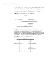
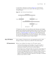
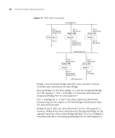
36 CHAPTER 4: USING RESILIENCE FEATURES As an example, Figure 8 shows a network containing three LAN segments separated by three bridges. With this configuration, each segment can communicate with the others using two paths. Without STP enabled, this configuration creates loops that cause the network to overload. Figure 8 A network configuration that creates loops Figure 9 shows the result of enabling STP on the bridges in the configuration. STP detects the duplicate paths and prevents, or blocks, one of them from forwarding traffic, so this configuration will work satisfactorily. STP has determined that traffic from LAN segment 2 to LAN segment 1 can only flow through Bridges C and A, because, for example, this path has a greater bandwidth and is therefore more efficient. Figure 9 Traffic flowing through Bridges C and A
-
 1
1 -
2
-
3
-
4
-
5
-
6
-
7
-
8
-
9
-
10
-
11
-
12
-
13
-
14
-
15
-
16
-
17
-
18
-
19
-
20
-
21
-
22
-
23
-
24
-
25
-
26
-
27
-
28
-
29
-
30
-
 31
31 -
 32
32 -
 33
33 -
 34
34 -
 35
35 -
 36
36 -
 37
37 -
 38
38 -
 39
39 -
 40
40 -
 41
41 -
42
-
43
-
44
-
45
-
46
-
47
-
48
-
49
-
50
-
51
-
52
-
53
-
54
-
55
-
56
-
57
-
58
-
59
-
60
-
61
-
62
-
63
-
64
-
65
-
66
-
67
-
68
-
69
-
70
-
71
-
72
-
73
-
74
-
75
-
76
-
77
-
78
-
79
-
80
-
81
-
82
-
83
-
84
-
85
-
86
-
87
-
88
-
89
-
90
-
91
-
92
-
93
-
94
-
95
-
96
-
97
-
98
-
99
-
100
-
101
-
102
 |
 |
