3Com 3C17203 Getting Started Guide
3Com 3C17203 - SuperStack 3 Switch 4400 Manual
 |
UPC - 662705363738
View all 3Com 3C17203 manuals
Add to My Manuals
Save this manual to your list of manuals |
3Com 3C17203 manual content summary:
- 3Com 3C17203 | Getting Started Guide - Page 1
SuperStack® 3 Switch 4400 Getting Started Guide 3C17203 3C17204 3C17206 http://www.3com.com/ Part No. DUA1720-3AAA03 Published March 2002 - 3Com 3C17203 | Getting Started Guide - Page 2
to you in conjunction with, this User Guide. Unless otherwise indicated, 3Com registered trademarks are registered in the United States and may or may not be registered in other countries. 3Com and SuperStack are registered trademarks of 3Com Corporation. The 3Com logo and CoreBuilder are trademarks - 3Com 3C17203 | Getting Started Guide - Page 3
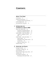
4400 About the Switch 4400 12 Summary of Hardware Features 12 Summary of Software Features 13 Switch 4400 - Front View Detail 14 10BASE-T/ 100BASE-TX Ports 15 LEDs 15 Switch 4400 - Rear View Detail 17 Power Socket 18 Redundant Power System Socket 18 Console Port 18 Expansion Module Slots 18 Default - 3Com 3C17203 | Getting Started Guide - Page 4
Power System 27 Choosing the Correct Cables 27 3 SETTING UP FOR MANAGEMENT Setting Up Overview 30 IP Configuration 30 Preparing for Management 32 Initial Switch Setup 32 Manual Setup 33 Connecting to a Front Panel Port 33 Connecting to the Console Port 35 Automatic Setup 38 Using 3Com Network - 3Com 3C17203 | Getting Started Guide - Page 5
Assignments 60 C TECHNICAL SPECIFICATIONS Switch 4400 (24-port) 63 Switch 4400 (48-port) 65 D TECHNICAL SUPPORT Online Technical Services 67 World Wide Web Site 67 3Com Knowledgebase Web Services 67 3Com FTP Site 68 Support from Your Network Supplier 68 Support from 3Com 68 Returning Products for - 3Com 3C17203 | Getting Started Guide - Page 6
- 3Com 3C17203 | Getting Started Guide - Page 7
you need to install and use a SuperStack® 3 Switch 4400 in its default state. This guide is intended for use with Switch 4400 models: ■ 3C17203 and 3C17206 - 24 10BASE-T/100BASE-TX ports ■ 3C17204 - 48 10BASE-T/100BASE-TX ports All procedures described in this guide apply to all models. The - 3Com 3C17203 | Getting Started Guide - Page 8
, use the following syntax: system password Commands In this example, you must supply a password for . The word "command" means that you must enter the command exactly as shown and then press Return or Enter. Commands appear in bold. Example: To display port information - 3Com 3C17203 | Getting Started Guide - Page 9
Documentation In addition to this guide, each Switch documentation set includes the following: ■ SuperStack 3 Switch Implementation Guide This guide contains information on the features supported by your Switch and how they can be used to optimize your network. It is supplied in PDF format on the - 3Com 3C17203 | Getting Started Guide - Page 10
maintain the structure of the files. You can register your SuperStack 3 Switch 4400 on the 3Com Web site: http://support.3com.com/registration/frontpg.pl Your suggestions are very important to us. They will help make our documentation more useful to you. Please e-mail comments about this document to - 3Com 3C17203 | Getting Started Guide - Page 11
THE SUPERSTACK 3 SWITCH 4400 This chapter contains introductory information about the Switch 4400 and how it can be used in your network. It covers summaries of hardware and software features and also the following topics: ■ About the Switch 4400 ■ Switch 4400 - Front View Detail ■ Switch 4400 - 3Com 3C17203 | Getting Started Guide - Page 12
Features Table 3 summarizes the hardware features that are supported by the Switch 4400. Table 3 Hardware features Feature Switch 4400 Addresses ■ Up to 8000 supported ■ Up to 64 permanent entries Auto-negotiation ■ Supported on all ports ■ Auto MDI/MDI-X Forwarding Modes Store and - 3Com 3C17203 | Getting Started Guide - Page 13
Support Quality of Service (QoS) RMON Email Notification of Events Management Port Security Switch 4400 Supported Supported Supported stack-wide Supported Support for up to 60 VLANs using the IEEE 802.1Q standard ■ 128 Multicast filter groups supported ■ IGMP filtering supported Supported Supported - 3Com 3C17203 | Getting Started Guide - Page 14
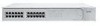
14 CHAPTER 1: INTRODUCING THE SUPERSTACK 3 SWITCH 4400 Switch 4400 - Front View Detail Figure 1 Switch 4400 / 4400 SE - front view 1 Figure 2 Switch 4400 / 4400 SE - front view 2 The appearance of the overlays in Figure 1 and Figure 2 differ but the functionality is identical for both Switches. - 3Com 3C17203 | Getting Started Guide - Page 15
- Front View Detail 15 Figure 3 Switch 4400 (48-port) - front view WARNING: RJ-45 Ports. These are shielded RJ-45 data sockets. They cannot be used as standard traditional telephone sockets, or to connect the unit to a traditional PBX or public telephone network. Only connect RJ-45 data connectors - 3Com 3C17203 | Getting Started Guide - Page 16
not been determined or there is no Link for a single port Module. Yellow flashing A Module is installed, however, it is not supported. Off The Module is not installed. Unit LEDs 1-8 Green When the Switch forms a stack with other Switch 4400 units, the LED indicates the position of the unit in - 3Com 3C17203 | Getting Started Guide - Page 17
-port) 1,2,3,4,8,7,6,5 (48-port) Green flashing The Switch physically forms a stack with other Switch 4400 units, but cannot be managed as part of that stack until all units have been upgraded to software version 2.0 or later. Off A fault has occurred. Power/Self Test LED Green The Switch is - 3Com 3C17203 | Getting Started Guide - Page 18
for both Switches. Power Socket The Switch automatically adjusts its power setting to any supply voltage in the range 90-260 VAC. Redundant Power To protect against internal power supply failure, you can use this socket System Socket to connect a Switch 4400 to a SuperStack 3 Advanced Redundant - 3Com 3C17203 | Getting Started Guide - Page 19
-Sensing Enabled Webcache Support Disabled Quality of Service (QoS) All ports prioritize NBX VoIP traffic (LAN and IP). All ports set to "best effort" for all other traffic. Webcache support and Quality of Service (QoS) are not available on the SuperStack 3 Switch 4400 SE unless the product - 3Com 3C17203 | Getting Started Guide - Page 20
20 CHAPTER 1: INTRODUCING THE SUPERSTACK 3 SWITCH 4400 - 3Com 3C17203 | Getting Started Guide - Page 21
of Each Other ■ The Power-up Sequence WARNING: Safety Information. Before installing or removing any components from the Switch 4400 or carrying out any maintenance de ce guide. VORSICHT: Sicherheitsinformationen. Bevor Sie Komponenten aus dem Switch 4400 entfernen oder dem Switch 4400 hinzufuegen - 3Com 3C17203 | Getting Started Guide - Page 22
unit ■ CD-ROM ■ Getting Started Guide (this guide) ■ Management Quick Reference Guide ■ Release Notes ■ Unit Information Labels ■ Warranty Information ■ Power Cord ■ 2 x Mounting brackets ■ 4 x Screws ■ 4 x Rubber feet Choosing a Suitable Site The Switch is suited for use on a desktop, either free - 3Com 3C17203 | Getting Started Guide - Page 23
of conductive (electrical) dust, for example laser printers. ■ The AC supply used by the Switch is separate to that used by units that generate high levels of AC noise, for example air conditioning units and laser printers. Rack-mounting The Switch 4400 is 1U high and will fit in most standard 19 - 3Com 3C17203 | Getting Started Guide - Page 24
and tighten with a suitable screwdriver. You must use the screws supplied with the mounting brackets. Damage caused to the unit by using incorrect screws invalidates your warranty. 4 Repeat steps 2 and 3 for the other side of the Switch. 5 Insert the Switch into the 19-inch rack and secure with - 3Com 3C17203 | Getting Started Guide - Page 25
of the upper unit line up with the recesses of the lower unit. Stacking Units Switch 4400 units can be stacked together and then treated as a single manageable unit with one IP address. Any combination of 24-port and 48-port units is allowed in a single stack, as long as the total number of front - 3Com 3C17203 | Getting Started Guide - Page 26
your Switch 4400 powered-up and ready for operation. Powering-up the Use the following sequence of steps to power-up the Switch. Switch 4400 1 Plug the power cord into the power socket at the rear of the Switch. 2 Plug the other end of the power cord into your power outlet. The Switch powers-up - 3Com 3C17203 | Getting Started Guide - Page 27
only method of connecting or disconnecting mains power is by connecting or disconnecting the power cord. CAUTION: The Switch can only use a SuperStack Advanced Redundant Power System output. Choosing the Correct Cables All of the ports on the front of the Switch 4400 are Auto-MDIX, that is they - 3Com 3C17203 | Getting Started Guide - Page 28
using a Category 5E or Category 6 cable, 3Com recommends that you briefly connect the cable to a grounded port before connecting network equipment. If you do not, the cable's Electrostatic Discharge (ESD) may damage the Switch's port. You can create a grounded port by connecting all wires at one end - 3Com 3C17203 | Getting Started Guide - Page 29
software to manage a Switch. It covers the following topics: ■ Setting Up Overview ■ Initial Switch Setup ■ Manual Setup ■ Automatic Setup ■ Methods of Managing a Switch ■ Setting Up Command Line Interface Management ■ Setting Up Web Interface Management ■ Setting Up SNMP Management ■ Default Users - 3Com 3C17203 | Getting Started Guide - Page 30
Switch. For more information on default users and changing default passwords, see "Default Users and Passwords" on page 46. IP Configuration You can use one of the following methods to allocate IP information to your Switch (essential if you wish to manage your Switch across the network). Manual IP - 3Com 3C17203 | Getting Started Guide - Page 31
to manually reconfigure the Switch. If you use the automatic IP configuration method, you need to view the automatically allocated IP information before you can begin management. Work through the "Automatic Setup" section on page 38 and use 3Com Network Supervisor or connect to the console port to - 3Com 3C17203 | Getting Started Guide - Page 32
Table 9. Table 9 Initial Switch Setup Methods Manual Setup Automatic Setup Connecting to a front panel port Use the web interface to manually enter IP information by accessing the Switch using its default IP address 169.254.100.100. Using 3Com Network Supervisor Use 3Com Network Supervisor to - 3Com 3C17203 | Getting Started Guide - Page 33
44. ■ You need to have the following so that you can manually set up the Switch with IP information: ■ IP address ■ subnet mask ■ default gateway Connecting the Workstation to the Switch 1 Connect the workstation to a front panel port using an Ethernet cable as shown in Figure 7. Figure 7 Connecting - 3Com 3C17203 | Getting Started Guide - Page 34
You are now ready to manually set up the Switch with IP information using the Web interface. 1 Power-up the Switch. This takes approximately one minute. 2 Open a suitable Web browser and enter 169.254.100.100 in the Location Address field. This is the default IP address that is automatically - 3Com 3C17203 | Getting Started Guide - Page 35
59. ■ You need to have the following so that you can manually set up the Switch with IP information: ■ IP address ■ subnet mask ■ default gateway Connecting the Workstation to the Switch 1 Connect the workstation to the console port using a standard null modem cable as shown in Figure 8. Figure - 3Com 3C17203 | Getting Started Guide - Page 36
the other end of the cable to one of the serial ports (also known as a COM port) on your workstation. 2 Open your terminal emulation software and configure the COM port settings to which you have connected the cable. The settings should be set to match the default settings for the Switch, which are - 3Com 3C17203 | Getting Started Guide - Page 37
and the Switch is ready for you to set up your chosen management method. See "Methods of Managing a Switch" on page 41. If you do not intend to use the command line interface via the console port to manage the Switch, you can disconnect the serial cable and close the terminal emulator software. - 3Com 3C17203 | Getting Started Guide - Page 38
to the Switch using the command line interface (CLI). Using 3Com Network Supervisor You can use the 3Com Network Supervisor application provided on the CD-ROM that accompanies your Switch to discover the automatically allocated IP information. 1 Connect your Switch to the network. 2 Power-up the - 3Com 3C17203 | Getting Started Guide - Page 39
the other end of the cable to one of the serial ports (also known as a COM port) on your workstation. 2 Open your terminal emulation software and configure the COM port settings to which you have connected the cable. The settings should be set to match the default settings for the Switch, which are - 3Com 3C17203 | Getting Started Guide - Page 40
sequence begins as soon as the Switch detects a connection to its console port. If the login prompt does not begin immediately, press Return a few times until it starts. 3 At the login and password prompts, enter admin as your user name and press Return at the password prompt. If you have logged on - 3Com 3C17203 | Getting Started Guide - Page 41
41. If you do not intend to use the command line interface via the console port to manage the Switch, you can disconnect the serial cable and close the terminal emulator software. Methods of Managing a Switch Once you have completed the initial set up of your Switch, you can decide how you wish to - 3Com 3C17203 | Getting Started Guide - Page 42
Each Switch has an internal set of web pages that allow you to manage Management the Switch using a Web browser remotely over an IP network For example, you can use the 3Com Network Supervisor software that is provided on the CD-ROM that accompanies your Switch. Figure 15 SNMP management - 3Com 3C17203 | Getting Started Guide - Page 43
is the IP address of the Switch) If opening a Telnet session via third party software you will need to enter the IP address in the format suitable for that software. 5 At the login and password prompts, enter admin as your user name and press Return at the password prompt (or the password of your - 3Com 3C17203 | Getting Started Guide - Page 44
Style Sheets must be enabled on your browser. These features are enabled on a browser by default. You will only need to enable them if you have changed your browser settings. Web Management To manage a Switch using the web interface over an IP network: Over the Network 1 Check that you have the - 3Com 3C17203 | Getting Started Guide - Page 45
are installed on the management workstation. ■ The management workstation is connected to the Switch using a port in VLAN 1 (the Default VLAN). By default, all ports on the Switch are in VLAN 1. You can use the 3Com Network Supervisor application that is provided on the CD-ROM that accompanies your - 3Com 3C17203 | Getting Started Guide - Page 46
the default passwords using either: ■ The security device user modify command on the CLI, or ■ The Security > Device > User > Modify operation on the web interface. For more information about default users and passwords, refer to the "Superstack 3 Switch Management Interface Reference Guide" on - 3Com 3C17203 | Getting Started Guide - Page 47
Indicated by LEDs ■ Solving Hardware Problems ■ Solving Communication Problems ■ Solving Software Upgrade Problems If you experience a problem that is not listed here, it may be included in the support section of the Superstack 3 Switch Management Interface Reference Guide on the CD-ROM that - 3Com 3C17203 | Getting Started Guide - Page 48
port does not light Check that: ■ The Switch and the device at the other end of the link (or cable) are connected securely. ■ The devices at both ends of the link are powered-up ■ The quality of cable is satisfactory ■ Auto-negotiation settings are the same at both ends. Auto-negotiation problems - 3Com 3C17203 | Getting Started Guide - Page 49
Problems 49 The Unit LED is flashing green The Switch unit physically forms a stack with other Switch 4400 units, but cannot be managed as part of that stack because one or more units have not been upgraded to software version 2.0 or later. You must upgrade each unit in the stack to this software - 3Com 3C17203 | Getting Started Guide - Page 50
If you experience communication problems with the Switch, ensure that: ■ The Switch IP address has been configured as described in Chapter 3. ■ If the Switch is separated from your management application by a router, ensure that the default gateway IP address within the Switch is the same as - 3Com 3C17203 | Getting Started Guide - Page 51
in house' only. These suggested IP addresses are part of a group of IP addresses that have been set aside specially for use 'in house' only. Solving Software Upgrade Problems You can upgrade the management software of the Switch by using the System > Control > Software Upgrade operation in the Web - 3Com 3C17203 | Getting Started Guide - Page 52
52 CHAPTER 4: PROBLEM SOLVING - 3Com 3C17203 | Getting Started Guide - Page 53
must read the following safety information before carrying out any installation or removal of components, or any maintenance procedures on the Switch 4400. WARNING: Warnings contain directions that you must follow for your personal safety. Follow all directions carefully. You must read the following - 3Com 3C17203 | Getting Started Guide - Page 54
installing the Switch 4400 in a stack with SuperStack II or SuperStack 3 units that are narrower than the 4400, the Switch 4400 unit must be installed below the narrower units. WARNING: The unit must be earthed (grounded). WARNING: Connect the unit to an earthed power supply to ensure compliance - 3Com 3C17203 | Getting Started Guide - Page 55
unit must be powered by 230V (2P+T) via an isolation transformer ratio 1:1, with the secondary connection point labelled Neutral, connected directly to earth (ground). †Impédance à la terre. WARNING: U.K. only: If connecting a modem to the console port of the Switch 4400, only use a modem which is - 3Com 3C17203 | Getting Started Guide - Page 56
56 APPENDIX A: SAFETY INFORMATION AVERTISSEMENT: Vous devez mettre l'appareil à la terre (à la masse) ce groupe. AVERTISSEMENT: Brancher l'unité à une source de courant mise à la terre pour assurer la conformité aux normes de sécurité. AVERTISSEMENT: Cordon électrique: Il doit être agréé ans le - 3Com 3C17203 | Getting Started Guide - Page 57
und der Ausbau des Geräts darf nur durch Fachpersonal erfolgen. VORSICHT: Wenn die Switch 4400 Einheit in einer Stapel mit anderen SuperStack 3 Hub Einheiten eingebaut werden soll, muß die Switch 4400 Einheit unter die schmaleren Hub Einheiten eingebaut werden. VORSICHT: Das Gerät muß geerdet sein - 3Com 3C17203 | Getting Started Guide - Page 58
sind nur gegeben, wenn auch die an das Gerät angeschlossenen Geräte unter SELV-Bedingungen betrieben werden. VORSICHT: RJ-45-Porte. Diese Porte sind geschützte Datensteckdosen. Sie dürfen weder wie normale traditionelle Telefonsteckdosen noch für die Verbindung der Einheit mit einem traditionellem - 3Com 3C17203 | Getting Started Guide - Page 59
B PIN-OUTS Null Modem Cable 9-pin to RS-232 25-pin PC-AT Serial Cable 9-pin to 9-pin - 3Com 3C17203 | Getting Started Guide - Page 60
Pin assignments are identical for 10BASE-TX and 100BASE-T RJ-45 connectors. Table 11 Pin assignments Pin Number Signal Ports configured as MDI 1 Transmit Data + 2 Transmit Data + 3 Receive Data + 4 Not assigned 5 Not assigned 6 Receive Data - 7 Not assigned 8 Not assigned - 3Com 3C17203 | Getting Started Guide - Page 61
Table 12 Pin assignments Pin Number Signal Ports configured as MDIX 1 Receive Data + 2 Receive Data - 3 Transmit Data + 4 Not assigned 5 Not assigned 6 Transmit Data 7 Not assigned 8 Not assigned RJ-45 Pin Assignments 61 Function - 3Com 3C17203 | Getting Started Guide - Page 62
62 APPENDIX B: PIN-OUTS - 3Com 3C17203 | Getting Started Guide - Page 63
C TECHNICAL SPECIFICATIONS Switch 4400 (24-port) Physical Dimensions Environmental Requirements Operating Temperature Storage Temperature Operating Humidity Standards Safety Agency Certifications EMC Emissions Immunity Heat Dissipation Power Supply AC Line Frequency Input Voltage Options Current - 3Com 3C17203 | Getting Started Guide - Page 64
APPENDIX C: TECHNICAL SPECIFICATIONS Standards Supported SNMP SNMP protocol (RFC 1157) MIB-II (RFC 1213) Bridge MIB (RFC 1493) RMON MIB II (RFC 2021) Remote Monitoring MIB (RFC 1757) MAU MIB (RFC 2239) Terminal Emulation Telnet (RFC 854) Protocols Used for Administration UDP (RFC 768) IP (RFC 791 - 3Com 3C17203 | Getting Started Guide - Page 65
Switch 4400 (48-port) Physical Dimensions Environmental Requirements Operating Temperature Storage Temperature Operating Humidity Standards Safety Agency Certifications EMC Emissions Immunity Heat Dissipation Power Supply AC Line Frequency Input Voltage Options Current Rating Standards Supported - 3Com 3C17203 | Getting Started Guide - Page 66
66 APPENDIX C: TECHNICAL SPECIFICATIONS - 3Com 3C17203 | Getting Started Guide - Page 67
browser: http://www.3com.com/ This service provides access to online support information such as technical documentation and software, as well as support options that range from technical education to maintenance and professional services. 3Com Knowledgebase Web Services The 3Com Knowledgebase is - 3Com 3C17203 | Getting Started Guide - Page 68
TECHNICAL SUPPORT 3Com FTP Site Download drivers, patches, software, and MIBs across the Internet from the 3Com public FTP site. This service is available 24 hours a day, 7 days a week. To connect to the 3Com FTP site, enter the following information into your FTP client: ■ Hostname: ftp.3com.com - 3Com 3C17203 | Getting Started Guide - Page 69
software, including revision levels ■ Diagnostic error messages ■ Details about recent configuration changes, if applicable Here is a list of worldwide technical telephone support numbers. These numbers are correct at the time of publication. Refer to the 3Com countries, you may use the toll-free - 3Com 3C17203 | Getting Started Guide - Page 70
70 APPENDIX D: TECHNICAL SUPPORT Returning Products for Repair Before you send a product directly to 3Com for repair, you must first obtain an authorization number. Products sent to 3Com without authorization numbers will be returned to the sender unopened, at the sender's expense. To obtain an - 3Com 3C17203 | Getting Started Guide - Page 71
Country U.S.A. and Canada Telephone Number 1 800 NET 3Com (1 800 638 3266) Enterprise Customers: 1 800 876 3266 Returning Products for Repair 71 Fax Number 1 408 326 7120 (not toll-free) - 3Com 3C17203 | Getting Started Guide - Page 72
72 APPENDIX D: TECHNICAL SUPPORT - 3Com 3C17203 | Getting Started Guide - Page 73
a default user 46 M MAC address of the Switch 24 management methods 41 preparing for 32 setting up 29, 30 manual setup 33 console port 35 front panel port 33 MDI configuration 27 MDIX configuration 27 MIBs 68 N network supplier support 68 O online technical services 67 P passwords of default users - 3Com 3C17203 | Getting Started Guide - Page 74
18 software features 13 specifications, system 63 stacking a Switch 4400 25 straight-through configuration 27 Switch 4400 3C number 24 automatic setup 38 console port 18 dimensions 63 Ethernet address 24 features 12, 13 initial setup 32 installation 21, 22 MAC address 24 manual setup 33 power socket - 3Com 3C17203 | Getting Started Guide - Page 75
energy and, if not installed and used in accordance with the instructions, may cause harmful interference to radio communications. Operation of this equipment in a residential area is likely to cause harmful interference to radio communications, in which case the user will be required to correct the - 3Com 3C17203 | Getting Started Guide - Page 76
-
 1
1 -
 2
2 -
 3
3 -
 4
4 -
 5
5 -
 6
6 -
 7
7 -
8
-
9
-
10
-
11
-
12
-
13
-
14
-
15
-
16
-
17
-
18
-
19
-
20
-
21
-
22
-
23
-
24
-
25
-
26
-
27
-
28
-
29
-
30
-
31
-
32
-
33
-
34
-
35
-
36
-
37
-
38
-
39
-
40
-
41
-
42
-
43
-
44
-
45
-
46
-
47
-
48
-
49
-
50
-
51
-
52
-
53
-
54
-
55
-
56
-
57
-
58
-
59
-
60
-
61
-
62
-
63
-
64
-
65
-
66
-
67
-
68
-
69
-
70
-
71
-
72
-
73
-
74
-
75
-
76
 |
 |

Part No. DUA1720-3AAA03
Published March 2002
SuperStack
®
3
Switch 4400
Getting Started Guide
3C17203
3C17204
3C17206