AMD ADA4200DAA5BV Builders Guide - Page 15
Ensure Proper Contact Between Backplate and Motherboard - difference between and
 |
UPC - 683728133160
View all AMD ADA4200DAA5BV manuals
Add to My Manuals
Save this manual to your list of manuals |
Page 15 highlights
31684 Rev. 3.00 September 2004 Builder's Guide for AMD Athlon™ 64 ProcessorBased Desktops and Workstations Figure 7. Ensure Proper Contact Between Backplate and Motherboard Note: The processor socket may be different from the socket pictured in Figure 7, depending on the version of the AMD Athlon 64 processor being used. 7. Carefully place the retention frame on the motherboard. 8. The screw holes must align with the backplate standoffs. (See Figure 8.) Figure 8. Retention Frame Screw Holes Aligned with Backplate Standoffs 9. Place the screws and tighten down the retention frame. (See Figure 9 on page 16.) − Ensure that the retention frame is flat with the motherboard. − Do not over-tighten the screws. Chapter 3 Heatsink Installation 15
-
 1
1 -
2
-
3
-
4
-
5
-
6
-
7
-
8
-
9
-
 10
10 -
 11
11 -
 12
12 -
 13
13 -
 14
14 -
 15
15 -
 16
16 -
 17
17 -
 18
18 -
 19
19 -
 20
20 -
21
-
22
-
23
-
24
-
25
-
26
-
27
-
28
-
29
-
30
-
31
-
32
-
33
-
34
-
35
-
36
-
37
-
38
-
39
-
40
-
41
-
42
-
43
-
44
-
45
-
46
 |
 |

31684
Rev. 3.00
September 2004
Builder’s Guide for AMD Athlon™ 64 Processor-
Based Desktops and Workstations
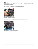
Figure 7. Ensure Proper Contact Between Backplate and Motherboard
Note:
The processor socket may be different from the socket pictured in Figure 7, depending on
the version of the AMD Athlon 64 processor being used.
7.
Carefully place the retention frame on the motherboard.
8.
The screw holes must align with the backplate standoffs. (See Figure 8.)
Figure 8. Retention Frame Screw Holes Aligned with Backplate Standoffs
9.
Place the screws and tighten down the retention frame. (See Figure 9 on page 16.)
−
Ensure that the retention frame is flat with the motherboard.
−
Do not over-tighten the screws.
Chapter 3
Heatsink Installation
15