AMD ADA4200DAA5BV Builders Guide - Page 5

List of s, Builder's Guide for AMD Athlon™ 64 Processor, Based Desktops and Workstations

Page 5 highlights

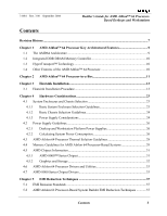
31684 Rev. 3.00 September 2004 Builder's Guide for AMD Athlon™ 64 ProcessorBased Desktops and Workstations List of Figures Figure 1. AMD Athlon™ 64 Processor Architecture 9 Figure 2. AMD Athlon 64 Processor-in-a-Box 11 Figure 3. AMD Athlon 64 FX Processor-in-a-Box 12 Figure 4. Retention Frame and Backplate for the AMD Athlon 64 Processor Heatsink 13 Figure 5. Backplate Release Liner 14 Figure 6. Motherboard Placed Over Backplate 14 Figure 7. Ensure Proper Contact Between Backplate and Motherboard 15 Figure 8. Retention Frame Screw Holes Aligned with Backplate Standoffs 15 Figure 9. Tightening Down the Retention Frame 16 Figure 10. Alignment Markers on Processor and Motherboard 16 Figure 11. Pushing Gently Down on the Processor 17 Figure 12. Plastic Cover Over Thermal Interface Material 17 Figure 13. Heatsink Centered Over Processor 18 Figure 14. Heatsink Spring Clip ...18 Figure 15. Pushing Straight Down on the Clip 19 Figure 16. Correctly Installed Spring Clip 19 Figure 17. Turning the Cam Lever 20 Figure 18. Cam Lever in Installed Position 20 Figure 19. Installed Heatsink ...21 Figure 20. Desirable Airflow-Power Supply with Bottom Inlet 25 Figure 21. Undesirable Airflow-Power Supply with Front Inlet Only 25 List of Figures 5

  • 1
  • 2
  • 3
  • 4
  • 5
  • 6
  • 7
  • 8
  • 9
  • 10
  • 11
  • 12
  • 13
  • 14
  • 15
  • 16
  • 17
  • 18
  • 19
  • 20
  • 21
  • 22
  • 23
  • 24
  • 25
  • 26
  • 27
  • 28
  • 29
  • 30
  • 31
  • 32
  • 33
  • 34
  • 35
  • 36
  • 37
  • 38
  • 39
  • 40
  • 41
  • 42
  • 43
  • 44
  • 45
  • 46

31684
Rev. 3.00
September 2004
Builder’s Guide for AMD Athlon™ 64 Processor-
Based Desktops and Workstations
List of Figures
Figure 1. AMD Athlon™ 64 Processor Architecture
........................................................................
9
Figure 2. AMD Athlon 64 Processor-in-a-Box
................................................................................
11
Figure 3. AMD Athlon 64 FX Processor-in-a-Box
.........................................................................
12
Figure 4. Retention Frame and Backplate for the AMD Athlon 64 Processor Heatsink
.................
13
Figure 5. Backplate Release Liner
...................................................................................................
14
Figure 6. Motherboard Placed Over Backplate
................................................................................
14
Figure 7. Ensure Proper Contact Between Backplate and Motherboard
.........................................
15
Figure 8. Retention Frame Screw Holes Aligned with Backplate Standoffs
...................................
15
Figure 9. Tightening Down the Retention Frame
............................................................................
16
Figure 10. Alignment Markers on Processor and Motherboard
......................................................
16
Figure 11. Pushing Gently Down on the Processor
.........................................................................
17
Figure 12. Plastic Cover Over Thermal Interface Material
.............................................................
17
Figure 13. Heatsink Centered Over Processor
.................................................................................
18
Figure 14. Heatsink Spring Clip
......................................................................................................
18
Figure 15. Pushing Straight Down on the Clip
................................................................................
19
Figure 16. Correctly Installed Spring Clip
.......................................................................................
19
Figure 17. Turning the Cam Lever
..................................................................................................
20
Figure 18. Cam Lever in Installed Position
.....................................................................................
20
Figure 19. Installed Heatsink
...........................................................................................................
21
Figure 20. Desirable Airflow—Power Supply with Bottom Inlet
...................................................
25
Figure 21. Undesirable Airflow—Power Supply with Front Inlet Only
.........................................
25
List of Figures
5