AOC e1649Fwu Service Manual
AOC e1649Fwu Manual
 |
View all AOC e1649Fwu manuals
Add to My Manuals
Save this manual to your list of manuals |
AOC e1649Fwu manual content summary:
- AOC e1649Fwu | Service Manual - Page 1
Layout 18 6.1.Main Board 18 6.2.USB Board 20 7.Maintainability 21 7.1.Equipments and Tools Requirement 21 7.2.Trouble Shooting 22 8.Firmware and DDC Instruction 26 9.Monitor Exploded View 29 10.BOM List 30 SAFETY NOTICE ANY PERSON ATTEMPTING TO SERVICE THIS CHASSIS MUST FAMILIARIZE HIMSELF - AOC e1649Fwu | Service Manual - Page 2
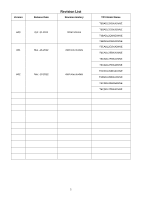
Version Release Date Revision List Revision History A00 Oct.-31-2011 Initial release A01 Mar.-13-2012 Add new models A02 Nov.-13-2012 Add new models TPV Model Name T6BADL2KBXA1NNE T6BADL2EBXA1NNE T6BADL2QBXE6NNE T6BADL2CBXA1NNE T6CADL2CBXA2NNE T6CADL2EBXA2NNE T6CADL2FBXA1NNE - AOC e1649Fwu | Service Manual - Page 3
by the service method selected. Hereafter throughout this manual, AOC Company will be referred to as AOC. WARNING Use Servicer assumes all liability. FOR PRODUCTS CONTAINING LASER: DANGER-Invisible laser radiation when open AVOID DIRECT EXPOSURE TO BEAM. CAUTION-Use of controls or adjustments - AOC e1649Fwu | Service Manual - Page 4
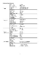
1.Monitor Specifications 4 - AOC e1649Fwu | Service Manual - Page 5
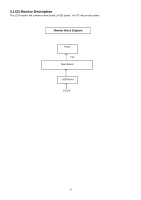
2.LCD Monitor Description The LCD monitor will contain a main board, a USB board,the PC will provide power. Monitor Block Diagram Panel 12V Main Board USB Board PC,5V 5 - AOC e1649Fwu | Service Manual - Page 6
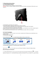
on page 16 to configure your USB Monitor. Note: Some computers may not provide enough power to the LCD monitor from one USB port. If so, connect the other USB connector on the Y end of the cable into another USB on your computer. 3.2 Control the Display You can use the AOC USB LCD monitor in mirror - AOC e1649Fwu | Service Manual - Page 7
the USB cable from the computer and monitor. 3.3 Setting the USB Monitor Follow this procedure to configure the AOC Monitor AOC USB monitor, it is also possible to use Windows Key ( a menu (and cycle through it) to switch mode. ) + P to display 3.4 new technology The AOC e1649Fwu monitor supports - AOC e1649Fwu | Service Manual - Page 8
Active Matrix Liquid Crystal Display composed of a TFT LCD panel, a driver circuit, and LED backlight system. The screen format is intended to support the 16:9 HD, 1366(H) x768(V) screen and 262k colors (RGB 6-bits data driver) with LED backlight driving circuit. All input signals are LVDS interface - AOC e1649Fwu | Service Manual - Page 9
Note 1:Maximum Measurement Condition:Black Pattern at 3.3V driving voltage. (Pmax=V3.3 x Iblack) Note 2:Measure Condition Note 3 : Maximum Measurement Condition 2:Black Pattern at 3.3V driving voltage, frame rate@75Hz. (Pmax=V3.3 x Iblack) 9 - AOC e1649Fwu | Service Manual - Page 10
Note: LVDS Signal Waveform LED array electrical characteristics Note 1: Calculator value for reference PLED = VF (Normal Distribution) * IF (Normal Distribution) / Efficiency Note 2: The LED life-time define as the estimated time to 50% degradation of initial luminous. 10 - AOC e1649Fwu | Service Manual - Page 11
4.4 Optical Characteristics Ta= 25°C 11 - AOC e1649Fwu | Service Manual - Page 12
+1.2V C755 100N 16V DGND VBUS0 C703 100N 16V C750 10uF 10V DGND R407 10 OHM 1/10W U708 1 2 3 VCC REF VIN LX 8 7 6 4 GND G4548-T0B-000-0050-101230 Key Component Date 03. Power Thursday , April 28, 2011 OEM MODEL USB power cordless TPV MODEL PCB NAME Sheet G4548-T0B-000-0050-1- - AOC e1649Fwu | Service Manual - Page 13
4 2 1 90OHM R711 NC USB_DN USB_DP 1 1 DGND +3V3 DGND USB / XTAL C417 100N 16V DGND +1V2 C418 100N 16V R417 USB_REF 3.48KOHM Date 04.DL-195 DVI_USB Thursday , April 28, 2011 OEM MODEL USB power cordless TPV MODEL PCB NAME Sheet G4548-T0B-000-0050-1-101230 1 of 7 Size Rev 称爹 C - AOC e1649Fwu | Service Manual - Page 14
16 UDQS LDQS /DDR_RAS 23 /DDR_CAS /DDR_WE 22 15 VDDQ 9 VDDQ VDDQ MVDD MVDD 3 33 18 1 MVDD NC NC 53 50 43 NC NC NC 42 25 19 NC CKE CLK 44 45 46 CLK VREF 49 DQ15 65 63 DQ14 DQ13 DQ12 DQ11 62 60 59 57 DQ10 DQ9 DQ8 56 54 13 DQ7 DQ6 DQ5 DQ4 11 10 USB power cordless TPV MODEL PCB NAME Sheet G4548- - AOC e1649Fwu | Service Manual - Page 15
NC/100OHM1/16W U408 NC/M25P128-VMF6TG 1 2 HOLD C 16 15 3 4 5 6 VCC D DU DU DU DU DU DU 14 13 12 11 7 DU DU 10 8 S Q VSS W 9 R473 R472 R431 NC/ 195 Power_Flash Thursday , April 28, 2011 OEM MODEL USB power cordless TPV MODEL PCB NAME Sheet G4548-T0B-000-0050-1-101230 1 of 7 Size Rev - AOC e1649Fwu | Service Manual - Page 16
4 90OHM 24 23 2 1 22 21 C476 NC C475 NC C474 NC C473 NC C472 NC C471 NC C470 NC C469 NC 20 19 18 17 16 15 14 13 12 DGND 11 10 R753 9 300 OHM 8 7 ace Thursday , April 28, 2011 OEM MODEL USB power cordless TPV MODEL PCB NAME Sheet G4548-T0B-000-0050-1-101230 1 of 7 Size - AOC e1649Fwu | Service Manual - Page 17
R002 NC USB_DN USB_DP 1 1 GND CN001 1 2 3 4 5 CONN GND 7 6 VBUS0 USB_DN USB_DP GND T P V ( Top Victory Electronics Co . , Ltd. ) Key Component Date 2. USB board Thursday , April 28, 2011 OEM MODEL AOC e1649Fwu TPV MODEL PCB NAME 715G Sheet 2 of 2 17 Size Rev 称爹 A C - AOC e1649Fwu | Service Manual - Page 18
6. PCB Layout 6.1 Main Board 715G4548M01000005I 18 - AOC e1649Fwu | Service Manual - Page 19
19 - AOC e1649Fwu | Service Manual - Page 20
6.3 USB Board 715G5071T01000004S 20 - AOC e1649Fwu | Service Manual - Page 21
7. Maintainability 7.1 Equipments and Tools Requirement 1. Voltmeter. 2. Oscilloscope. 3. Pattern Generator. 4. DDC Tool with an IBM Compatible Computer. 5. Alignment Tool. 6. LCD Color Analyzer. 7. Service Manual. 8. User Manual. 21 - AOC e1649Fwu | Service Manual - Page 22
7.2 Trouble Shooting 1.No Power No power Check power cable is tightened? OK NG Re-plug the power cable Check Power "On/Off" is "On"? NG Turn on the Power "On/Off" switch OK Check the LED indicate is OK? NG Check the AC power OK Replace the converter board NG Replace main board and check - AOC e1649Fwu | Service Manual - Page 23
(Power LED Blue) No Video (Power LED Blue) Press the power button is OK? OK Replace the converter board NG Replace the main board and connection NG Check the LVDS/FFC cable or panel NG Replace the key board NG Replace the main board OK The end OK The end OK Replace the LVDS/FFC cable or - AOC e1649Fwu | Service Manual - Page 24
3. DIM DIM (image overlap, focus or flicker) Reset in factory mode NG Set to the optimal frequency, select the recommended frequency NG Readjust the phase and pixel clock in the user mode NG Pull out signal cable and check "Self Test Feature Check" is ok? NG Replace the main board OK The end OK - AOC e1649Fwu | Service Manual - Page 25
is not optimal Color is not optimal Miss color Color shift Replace the signal cable NG OK The end Reset the factory mode NG In the user mode, set the" color settings" until customer satisfy Pull out the signal cable and check the screen color display is normal? NG OK NG Replace the - AOC e1649Fwu | Service Manual - Page 26
8. Firmware and DDC Instruction Don't burn HDCP-KEY 1. Install the newest driver (DLsetup_7.0M1.exe), the driver provided by the Display Link 2. Connect USB Monitor to PC, as the follow picture 3. Double-click the icon "DL1x0-DL1x5 Tester.exe" Choose "Program Firmware" 26 - AOC e1649Fwu | Service Manual - Page 27
Load Firmware 27 - AOC e1649Fwu | Service Manual - Page 28
Burning off software, USB Monitor can be displayed 28 - AOC e1649Fwu | Service Manual - Page 29
9. Monitor Exploded Views 29 - AOC e1649Fwu | Service Manual - Page 30
BARCODE 1 E1649FWU ID LABEL E1649FWU FRENCH LABEL E1649FWU POP LABEL e1649Fwu QSG EPS EPS ARTWORK CARTON E1649FWU EPE COVER RPOTECT BAG anti static electricity_tape e1649Fwu CD MANUAL FOOT PAD LABEL P.E. BAGx320x210x0.04 TIE (Y1900221) AL FOIL GASKET_ALUMINIUM FOIL FFC CABLE P0.5 40P 210MM USB BOARD - AOC e1649Fwu | Service Manual - Page 31
SOT-23 MOSFET AO3401A SOT-23 MOSFET AO3401A SOT-23 RST CHIPR MAX0R05 1/16W FENGHUA RST CHIPR MAX0R05 1/16W FENGHUA RST CHIPR 10 OHM +-1% 1/16W FENGHUA RST CHIPR 10 OHM +-1% 1/16W FENGHUA RST CHIPR 100 OHM +-5% 1/16W FENGHUA RST CHIPR 100 OHM +-5% 1/16W FENGHUA RST CHIPR 100 OHM +-5% 1/16W FENGHUA - AOC e1649Fwu | Service Manual - Page 32
1/16W FENGHUA RST CHIPR 75 OHM +-5% 1/16W FENGHUA RST CHIPR 75 OHM +-5% 1/16W FENGHUA RST CHIPR 75 OHM +-1% 1/16W FENGHUA RST CHIPR 10 OHM 5% 1/10W FENGHUA RST CHIPR 10 OHM 5% 1/10W FENGHUA RST CHIPR 3.48KOHM 1/10W FENGHUA RST CHIPR 475 OHM +-1% 1/10W FENGHUA RST CHIPR 11.5KOHM +-1% 1/8W FENGHUA RST - AOC e1649Fwu | Service Manual - Page 33
X7R +/-10% CAP 0402 100NF 10% 16V X7R CAP 0402 100NF 10% 16V X7R CAP 0402 100NF 10% 16V X7R CAP 0402 100NF 10% 16V X7R CAP 0402 100NF 10% 16V X7R CAP 0402 100NF 10% 16V X7R CAP 0402 100NF 10% 16V X7R CAP 0402 100NF 10% 16V X7R CAP 0402 100NF 10% 16V X7R CAP 0402 100NF 10% 16V - AOC e1649Fwu | Service Manual - Page 34
50V NPO +-5% YAGEO MLCC 0402 18pF 50V NPO +-5% YAGEO MLCC 0402 18pF 50V NPO +-5% YAGEO CAP CHIP 0402 220N 10V X5R +/-10% CAP 0603 1UF 10% 16V X7R CAP 0603 1UF 10% 16V X7R NO-SUGGEST CAP 0603 10uF 20% 6.3V X5R NO-SUGGEST CAP 0603 10uF 20% 6.3V X5R NO-SUGGEST CAP - AOC e1649Fwu | Service Manual - Page 35
709G4548 HS001 715G4548M01000005I NO-SUGGEST CAP 0805 10uF 10% 10V X5R NO-SUGGEST CAP 0805 10uF 10% 10V X5R NO-SUGGEST CAP 0805 10uF 10% 10V X5R NO-SUGGEST CAP 0805 10uF 10% 10V X5R NO-SUGGEST CAP 0805 10uF 10% 10V X5R NO-SUGGEST CAP 0805 10uF 10% 10V X5R NO-SUGGEST CAP 0805 10uF - AOC e1649Fwu | Service Manual - Page 36
C001 L001 CN001 CN002 E715 H52G 2191 1 H52G1701 1 065G040210412K Y 073G253S 6 M 033G8032 6F HR 088G 341902 CL 715G5071T01000004S MESH PRINTTING_PAPER CAP 0402 100NF 10% 16V X7R COMMON FILTER CHOKE 90 ohm HF CONNECTOR 6P 1.25 MINI USB CONN R/A 5P BLACK H=3.95 USB PCB FR4 DS 38.5*25*1.6MM 36
-
 1
1 -
 2
2 -
 3
3 -
 4
4 -
 5
5 -
 6
6 -
 7
7 -
8
-
9
-
10
-
11
-
12
-
13
-
14
-
15
-
16
-
17
-
18
-
19
-
20
-
21
-
22
-
23
-
24
-
25
-
26
-
27
-
28
-
29
-
30
-
31
-
32
-
33
-
34
-
35
-
36
 |
 |
15.6" LCD Monitor
AOC e1649Fwu
1
Table of Contents
Description
Page Description
Page
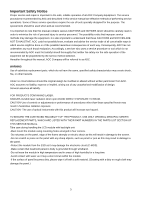
SAFETY NOTICE
ANY PERSON ATTEMPTING TO SERVICE THIS CHASSIS MUST FAMILIARIZE HIMSELF WITH THE
CHASSIS AND BE AWARE OF THE NECESSARY SAFETY PRECAUTIONS TO BE USED WHEN SERVICING
ELECTRONIC EQUIPMENT CONTAINING HIGH VOLTAGES.
Service
Service
Service
Table of Contents…………………
..
…………………
..
…
...1
Revision List.…
.......................................
............
……
......
2
Important Sa
fety Notice.…
.
…
..................
...........
……
......
3
1.Monitor Specification
..............................
……….
...........
4
2.
LCD Monitor Description………
.
…………………….
......
5
3.Operation Instruction.
…………
...............
....
…….
..........
6
3.1.
Connecting the Monitor
...............................
…
...........
6
3.2.
Control the Display
....................................................
6
3.3
.
Setting the USB Monitor
...........................................
7
3.4.new technology
..........................................
7
4 Panel Specification
……
........
.......
………………
.......
8
4.1.General Features
.......
........
……….
.................
8
4.2.General Specifications
……
..........................
8
4.3.Electrical Characteristics..
………………………
..8
4.4.Optical Characteristics..
………………………
..11
5
.Block Diagram…
............
.......................................
12
5.1.Main Board
…
..
…...
..........................................
17
5.2.USB Board
…
..
…...
..........................................
17
6
.PCB Layout..………
..............................................
18
6.1.Main Board
………
..
…
.............................
...........
18
6.2.USB Board
…
.
…
..............................................
20
7
.Maintainability……….
...........................................
21
7.1.Equipments and Tools Requirement
…
...............
21
7.2.
Trouble Shooting…
..
………
...............................
22
8.Firmware and DDC
Instruction………………
.
…
.26
9.Monitor Exploded
View……
......
..........................
29
10
.BOM List…………
..
……………………….
............
30
CAUTION: USE A SEPARATE ISOLATION TRANSFOMER FOR THIS UNIT WHEN SERVICING