ASRock X58 Extreme6 Quick Installation Guide - Page 38
English, 11 Dr. Debug - test
 |
View all ASRock X58 Extreme6 manuals
Add to My Manuals
Save this manual to your list of manuals |
Page 38 highlights
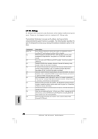
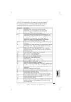
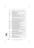
2.11 Dr. Debug Dr. Debug is used to provide code information, which makes troubleshooting even easier. Please see the diagrams below for reading the Dr. Debug codes. The Bootblock initialization code sets up the chipset, memory and other components before system memory is available. The following table describes the type of checkpoints that may occur during the bootblock initialization portion of the BIOS: Checkpoint Before D1 D1 D0 D2 D3 D4 D5 D6 D7 D8 D9 DA Description Early chipset initialization is done. Early super I/O initialization is done including RTC and keyboard controller. NMI is disabled. Perform keyboard controller BAT test. Check if waking up from power management suspend state. Save power-on CPUID value in scratch CMOS. Go to flat mode with 4GB limit and GA20 enabled. Verify the bootblock checksum. Disable CACHE before memory detection. Execute full memory sizing module. Verify that flat mode is enabled. If memory sizing module not executed, start memory refresh and do memory sizing in Bootblock code. Do additional chipset initialization. Re-enable CACHE. Verify that flat mode is enabled. Test base 512KB memory. Adjust policies and cache first 8MB. Set stack. Bootblock code is copied from ROM to lower system memory and control is given to it. BIOS now executes out of RAM. Both key sequence and OEM specific method is checked to determine if BIOS recovery is forced. Main BIOS checksum is tested. If BIOS recovery is necessary, control flows to checkpoint E0. Restore CPUID value back into register. The Bootblock-Runtime interface module is moved to system memory and control is given to it. Determine whether to execute serial flash. The Runtime module is uncompressed into memory. CPUID information is stored in memory. Store the Uncompressed pointer for future use in PMM. Copying Main BIOS into memory. Leaves all RAM below 1MB Read-Write including E000 and F000 shadow areas but closing SMRAM. Restore CPUID value back into register. Give control to BIOS POST (ExecutePOSTKernel). English 38 ASRock X58 Extreme6 Motherboard
-
 1
1 -
2
-
3
-
4
-
5
-
6
-
7
-
8
-
9
-
10
-
11
-
12
-
13
-
14
-
15
-
16
-
17
-
18
-
19
-
20
-
21
-
22
-
23
-
24
-
25
-
26
-
27
-
28
-
29
-
30
-
31
-
32
-
 33
33 -
 34
34 -
 35
35 -
 36
36 -
 37
37 -
 38
38 -
 39
39 -
 40
40 -
 41
41 -
 42
42 -
 43
43 -
44
-
45
-
46
-
47
-
48
-
49
-
50
-
51
-
52
-
53
-
54
-
55
-
56
-
57
-
58
-
59
-
60
-
61
-
62
-
63
-
64
-
65
-
66
-
67
-
68
-
69
-
70
-
71
-
72
-
73
-
74
-
75
-
76
-
77
-
78
-
79
-
80
-
81
-
82
-
83
-
84
-
85
-
86
-
87
-
88
-
89
-
90
-
91
-
92
-
93
-
94
-
95
-
96
-
97
-
98
-
99
-
100
-
101
-
102
-
103
-
104
-
105
-
106
-
107
-
108
-
109
-
110
-
111
-
112
-
113
-
114
-
115
-
116
-
117
-
118
-
119
-
120
-
121
-
122
-
123
-
124
-
125
-
126
-
127
-
128
-
129
-
130
-
131
-
132
-
133
-
134
-
135
-
136
-
137
-
138
-
139
-
140
-
141
-
142
-
143
-
144
-
145
-
146
-
147
-
148
-
149
-
150
-
151
-
152
-
153
-
154
-
155
-
156
-
157
-
158
-
159
-
160
-
161
-
162
-
163
-
164
-
165
-
166
-
167
-
168
-
169
-
170
-
171
-
172
-
173
-
174
-
175
-
176
-
177
-
178
-
179
-
180
-
181
-
182
-
183
-
184
-
185
-
186
-
187
-
188
-
189
-
190
-
191
-
192
-
193
-
194
-
195
-
196
-
197
-
198
-
199
-
200
-
201
-
202
-
203
-
204
-
205
-
206
-
207
-
208
-
209
-
210
-
211
-
212
-
213
-
214
-
215
-
216
-
217
-
218
-
219
-
220
-
221
-
222
-
223
-
224
-
225
-
226
-
227
-
228
-
229
-
230
-
231
-
232
-
233
-
234
-
235
-
236
-
237
-
238
-
239
-
240
-
241
-
242
-
243
-
244
-
245
-
246
-
247
-
248
-
249
-
250
-
251
-
252
-
253
-
254
-
255
-
256
-
257
-
258
-
259
-
260
-
261
-
262
-
263
-
264
-
265
-
266
-
267
-
268
-
269
-
270
-
271
-
272
-
273
-
274
-
275
-
276
-
277
-
278
-
279
-
280
-
281
-
282
-
283
-
284
-
285
-
286
-
287
-
288
-
289
-
290
-
291
-
292
-
293
 |
 |