ASRock Z68 Extreme4 Gen3 User Manual
ASRock Z68 Extreme4 Gen3 Manual
 |
View all ASRock Z68 Extreme4 Gen3 manuals
Add to My Manuals
Save this manual to your list of manuals |
ASRock Z68 Extreme4 Gen3 manual content summary:
- ASRock Z68 Extreme4 Gen3 | User Manual - Page 1
Z68 Extreme4 Gen3 User Manual Version 1.0 Published June 2011 Copyright©2011 ASRock INC. All rights reserved. 1 - ASRock Z68 Extreme4 Gen3 | User Manual - Page 2
by ASRock. ASRock assumes no responsibility for any errors or omissions that may appear in this manual. With respect to the contents of this manual, ASRock does The Lithium battery adopted on this motherboard contains Perchlorate, a toxic substance controlled in Perchlorate Best Management Practices - ASRock Z68 Extreme4 Gen3 | User Manual - Page 3
and CPU fan 19 2.5 Installation of Memory Modules (DIMM 20 2.6 Expansion Slots (PCI and PCI Express Slots 22 2.7 SLITM and Quad SLITM Operation Guide 23 2.8 CrossFireXTM, 3-Way CrossFireXTM and Quad CrossFireXTM Operation Guide 27 2.9 Dual Monitor and Surround Display Features 33 2.10 ASRock - ASRock Z68 Extreme4 Gen3 | User Manual - Page 4
ACPI Con guration 73 3.4.7 USB Con guration 74 3.5 Hardware Health Event Monitoring Screen 75 3.6 Boot Screen 76 3.7 Security Screen 77 3.8 Exit Screen 78 4 Software Support 79 4.1 Install Operating System 79 4.2 Support CD Information 79 4.2.1 Running Support CD 79 4.2.2 Drivers Menu 79 - ASRock Z68 Extreme4 Gen3 | User Manual - Page 5
about the model you are using. www.asrock.com/support/index.asp 1.1 Package Contents ASRock Z68 Extreme4 Gen3 Motherboard (ATX Form Factor: 12.0-in x 9.6-in, 30.5 cm x 24.4 cm) ASRock Z68 Extreme4 Gen3 Quick Installation Guide ASRock Z68 Extreme4 Gen3 Support CD 1 x Ribbon Cable for a 3.5-in Floppy - ASRock Z68 Extreme4 Gen3 | User Manual - Page 6
- Supports Intel® HD Graphics Built-in Visuals: Intel® Quick Sync Video, Intel® InTruTM 3D, Intel® Clear Video HD Technology, Intel® HD Graphics 2000/3000, Intel® Advanced Vector Extensions (AVX) - Pixel Shader 4.1, DirectX 11 with Intel® Ivy Bridge CPU, DirectX 10.1 with Intel® Sandy Bridge CPU - ASRock Z68 Extreme4 Gen3 | User Manual - Page 7
x RJ-45 LAN Port with LED (ACT/LINK LED and SPEED LED) - 1 x IEEE 1394 Port - 1 x Clear CMOS Switch with LED - HD Audio Jack: Rear Speaker/Central/Bass/Line in/Front Speaker/Microphone (see CAUTION 8) - 2 x SATA3 6.0 Gb/s connectors, support RAID (RAID 0, RAID 1, RAID 10, RAID 5, Intel Rapid Storage - ASRock Z68 Extreme4 Gen3 | User Manual - Page 8
- CPU/Chassis/Power FAN connector - 24 pin ATX power connector - 8 pin 12V power connector - SLI/XFire power connector - Front panel audio connector - 3 x USB 2.0 headers (support 6 USB 2.0 ports) - 1 x USB 3.0 header (supports 2 USB 3.0 ports) - 1 x Dr. Debug (7-Segment Debug LED) - 1 x Clear CMOS - ASRock Z68 Extreme4 Gen3 | User Manual - Page 9
ASRock SmartView (see CAUTION 12) - ASRock XFast USB (see CAUTION 13) - ASRock XFast LAN (see CAUTION 14) - Lucid Virtu (see CAUTION 15) - ASRock On/Off Play Technology (see CAUTION 16) - Hybrid Booster: - CPU Frequency Stepless Control (see CAUTION 17) - ASRock U-COP (see CAUTION 18) - Boot - ASRock Z68 Extreme4 Gen3 | User Manual - Page 10
motherboard supports Dual Channel Memory Technology. Before you implement Dual Channel Memory Technology, make sure to read the installation guide of memory modules on page 20 for proper installation. 3. DDR3 frequency options may depend on the processor. Only K-Series CPU can support DDR3 overclock - ASRock Z68 Extreme4 Gen3 | User Manual - Page 11
utility, you can press key during the POST or press key to BIOS setup menu to access ASRock Instant Flash. Just launch this tool and save the new BIOS le to your USB ash drive, oppy disk or hard drive, then you can update your BIOS only in a few clicks without preparing an additional oppy - ASRock Z68 Extreme4 Gen3 | User Manual - Page 12
motherboard also provides a free 3.5mm audio cable (optional) that ensures users the most convenient computing environment. 17. Although this motherboard offers stepless control different CPU cooler types, Socket LGA 775, LGA 1155 and LGA 1156. Please be noticed that not all the 775 and 1156 CPU Fan - ASRock Z68 Extreme4 Gen3 | User Manual - Page 13
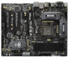
4a PCIE1 CHA_FAN2 1 CLRCMOS1 ErP/EuP Ready LAN PHY Super I/O Designed in Taipei AUDIO CODEC HD_AUDIO1 1 HDMI_SPDIF1 COM1 1 1 PCIE2 RoHS PCIE3 PCI Express 3.0 PCI1 Z68 Extreme4 Gen3 CMOS Battery PCIE4 XFast USB PCI2 DX10.1 Front USB 3.0 1394a FLOPPY1 PCIE5 IR1 1 FRONT_1394 1 USB6_7 - ASRock Z68 Extreme4 Gen3 | User Manual - Page 14
USB 3.0 Ports (USB45) IEEE 1394 Port (IEEE 1394) eSATA3 Connector Clear CMOS Switch (CLRCBTN) HDMI Port DVI-D Port PS/2 Keyboard Port (Purple) * There are two LED next to the LAN type of speaker you use. TABLE for Audio Output Connection Audio Output Channels Front Speaker Rear Speaker Central / - ASRock Z68 Extreme4 Gen3 | User Manual - Page 15
Multi-Streaming function, you need to connect a front panel audio cable to the front panel audio header. After restarting your computer, you will nd "Mixer" Front Speaker, or select "Realtek HDA Audio 2nd output" to use front panel audio. *** eSATA3 connector supports SATA Gen3 in cable 1M. 15 - ASRock Z68 Extreme4 Gen3 | User Manual - Page 16
. Do not over-tighten the screws! Doing so may damage the motherboard. 2.2 Pre-installation Precautions Take note of the following precautions before you install motherboard components or change any motherboard settings. 1. Unplug the power cord from the wall socket before touching any component - ASRock Z68 Extreme4 Gen3 | User Manual - Page 17
of Intel 1155-Pin CPU, please follow the steps below. Load Plate Load Lever Contact Array Socket Body 1155-Pin Socket Overview Before you insert the 1155-Pin CPU into the socket, please check if the CPU the PnP cap. 2. This cap must be placed if returning the motherboard for after service. 17 - ASRock Z68 Extreme4 Gen3 | User Manual - Page 18
key notches. orientation key notch alignment key Pin1 Pin1 orientation key notch 1155-Pin CPU alignment key 1155-Pin Socket For proper inserting, please ensure to match the two orientation key notches of the CPU with the two alignment keys of the socket. Step 3-3. Carefully place the - ASRock Z68 Extreme4 Gen3 | User Manual - Page 19
fan operation or contact other components. Please be noticed that this motherboard supports Combo Cooler Option (C.C.O.), which provides the exible option to adopt three different CPU cooler types, Socket LGA 775, LGA 1155 and LGA 1156. The white throughholes are for Socket LGA 1155/1156 CPU fan - ASRock Z68 Extreme4 Gen3 | User Manual - Page 20
Memory Modules (DIMM) This motherboard provides four 240-pin DDR3 (Double Data Rate 3) DIMM slots, and supports Dual Channel Memory Technology. For dual channel con guration, you always need to install identical (the same brand, speed, size and chip two memory modules, for optimal compatibility and - ASRock Z68 Extreme4 Gen3 | User Manual - Page 21
matches the break on the slot. notch break notch break The DIMM only ts in one correct orientation. It will cause permanent damage to the motherboard and the DIMM if you force the DIMM into the slot at incorrect orientation. Step 3. Firmly insert the DIMM into the slot until the retaining - ASRock Z68 Extreme4 Gen3 | User Manual - Page 22
a chassis fan to motherboard chassis fan connector (CHA_FAN1, CHA_FAN2 or CHA_FAN3) when using multiple graphics cards for better thermal environment. 5. To run the PCI Express in Gen 3 speed, please must install the Ivy Bridge CPU which supports PCI Express Gen3. If you install the Sandy Bridge CPU - ASRock Z68 Extreme4 Gen3 | User Manual - Page 23
ed. For Quad SLITM technology, you should have two identical Quad SLITM-ready graphics cards that are NVIDIA® certi ed. 2. Make sure that your graphics card driver supports NVIDIA® SLITM technology. Download the driver from NVIDIA® website (www.nvidia.com). 3. Make sure that your power supply unit - ASRock Z68 Extreme4 Gen3 | User Manual - Page 24
Step3. Align and insert ASRock SLI_Bridge_2S Card to the gold ngers on each graphics card. Make sure ASRock SLI_Bridge_2S Card is rmly in place. ASRock SLI_Bridge_2S Card Step4. Connect a VGA cable or a DVI cable to the monitor connector or the DVI connector of the graphics card that is inserted to - ASRock Z68 Extreme4 Gen3 | User Manual - Page 25
Installation and Setup Install the graphics card drivers to your system. After that, you can For SLITM mode only) A. Double-click NVIDIA Settings icon on your Windows® taskbar. B. From the pop-up menu, select Set SLI and PhysX configuration. In Set PhysX GPU acceleration item, please select Enabled. - ASRock Z68 Extreme4 Gen3 | User Manual - Page 26
From the pop-up menu, select All Programs, and then click NVIDIA Corporation. C. Select NVIDIA Control Panel tab. D. Select Control Panel tab. E. From the pop-up menu, select Set SLI and PhysX configuration. In Set PhysX GPU acceleration item, please select Enabled. In Select an SLI configuration item - ASRock Z68 Extreme4 Gen3 | User Manual - Page 27
CrossFireXTM driver updates. 1. If a customer incorrectly con gures their system they will not see the performance bene ts of CrossFireXTM. All three CrossFireXTM components, a CrossFireXTM Ready graphics card, a CrossFireXTM Ready motherboard and a CrossFireXTM Edition co-processor graphics card - ASRock Z68 Extreme4 Gen3 | User Manual - Page 28
Step 2. Connect two Radeon graphics cards by installing CrossFire Bridge on CrossFire Bridge Interconnects on the top of Radeon graphics cards. (CrossFire Bridge is provided with the graphics card you purchase, not bundled with this motherboard. Please refer to your graphics card vendor for details - ASRock Z68 Extreme4 Gen3 | User Manual - Page 29
Bridge to connect Radeon graphics cards on PCIE2 and PCIE4 slots, and use the other CrossFireTM Bridge to connect Radeon graphics cards on PCIE4 and PCIE5 slots. (CrossFireTM Bridge is provided with the graphics card you purchase, not bundled with this motherboard. Please refer to your graphics - ASRock Z68 Extreme4 Gen3 | User Manual - Page 30
CrossFireTM Bridge Step 5. Connect the DVI monitor cable to the DVI connector on the Radeon graphics card on PCIE2 slot. (You may use the DVI to D-Sub adapter to convert the DVI connector to D-Sub interface, and then connect the D-Sub monitor cable to the DVI to D-Sub adapter.) 30 - ASRock Z68 Extreme4 Gen3 | User Manual - Page 31
boot into OS. Remove the AMD driver if you have any VGA driver installed in your system. The Catalyst Uninstaller is an optional download. We recommend using this utility to uninstall any previously installed Catalyst drivers prior to installation. Please check AMD website for ATITM driver updates - ASRock Z68 Extreme4 Gen3 | User Manual - Page 32
. After restarting your computer, please con rm whether the option "Enable CrossFireTM" in "ATI Catalyst Control Center" is selected or not; if not, please select it again, and then you are able further information of AMD CrossFireXTM technology, please check AMD website for updates and details. 32 - ASRock Z68 Extreme4 Gen3 | User Manual - Page 33
to this motherboard. This motherboard also provides independent display controllers for DVI-D, D-Sub, HDMI and DisplayPort to support dual VGA output after your system boots. If you haven't installed onboard VGA driver yet, please install onboard VGA driver from our support CD to your system - ASRock Z68 Extreme4 Gen3 | User Manual - Page 34
connectors of the add-on PCI Express VGA cards on PCIE2, PCIE4 and PCIE5 slots. 3. Boot your system. Press or to enter UEFI setup. Enter "Onboard VGA Share Memory" option to adjust the memory capability to [32MB], [64MB], [128MB], [256MB] or [512MB] to enable the function of D-sub. Please - ASRock Z68 Extreme4 Gen3 | User Manual - Page 35
function is supported on this motherboard. To use HDCP function with this motherboard, you need to adopt the monitor that supports HDCP function as well. Therefore, you can enjoy the superior display quality with high-de nition HDCP encryption contents. Please refer to below instruction for more - ASRock Z68 Extreme4 Gen3 | User Manual - Page 36
is compatible with most of the chassis on the market. 3. The Multi-Angle CIR Receiver does not support Hot-Plug function. Please install it before you boot the system. * ASRock Smart Remote is only supported by some of ASRock motherboards. Please refer to ASRock website for the motherboard support - ASRock Z68 Extreme4 Gen3 | User Manual - Page 37
do not clear the CMOS right after you update the BIOS. If you need to clear the CMOS when you just nish updating the BIOS, you must boot up the system rst, and then shut it down before you do the clear-CMOS action. Please be noted that the password, date, time, user default pro le, 1394 GUID and MAC - ASRock Z68 Extreme4 Gen3 | User Manual - Page 38
jumper caps over the headers and connectors will cause permanent damage of the motherboard! FDD connector (33-pin FLOPPY1) (see p.13 No. 34) the connect to the power supply These four Serial ATA3 (SATA3) connectors support SATA data cables for internal storage devices. The current SATA3 interface - ASRock Z68 Extreme4 Gen3 | User Manual - Page 39
two default USB 3.0 ports on the I/O panel, there is one USB 3.0 header on this motherboard. This USB 3.0 header can support two USB 3.0 ports. This header supports an optional wireless transmitting and receiving infrared module. This header can be used to connect the remote controller receiver. 39 - ASRock Z68 Extreme4 Gen3 | User Manual - Page 40
cable that allows convenient connection and control of audio devices. 1. High De nition Audio supports Jack Sensing, but the panel wire on the chassis must support HDA to function correctly. Please follow the instruction in our manual and chassis manual to install your system. 2. If you use AC - ASRock Z68 Extreme4 Gen3 | User Manual - Page 41
by chassis. A front panel module mainly consists of power switch, reset switch, power LED, hard drive activity LED, speaker and etc. When +12V GND CPU Fan Connectors (4-pin CPU_FAN1) (see p.13 No. 4) FAN_SPEED_CONTROL 4 CPU_FAN_SPEED 3 +12V 2 GND 1 Please connect the CPU fan cable to the - ASRock Z68 Extreme4 Gen3 | User Manual - Page 42
) support, the 3-Pin CPU fan still can work successfully even without the fan speed control function. If you plan to connect the 3-Pin CPU fan to the CPU fan connector on this motherboard, please connect it to Pin 1-3. Pin 1-3 Connected 3-Pin Fan Installation (3-pin CPU_FAN2) (see p.13 No. 5) ATX - ASRock Z68 Extreme4 Gen3 | User Manual - Page 43
there is one IEEE 1394 header (FRONT_1394) on this motherboard. This IEEE 1394 header can support one IEEE 1394 port. This COM1 header supports a serial port module. HDMI_SPDIF Header (2-pin HDMI_SPDIF1) (see p.13 No. 37) 1 GND SPDIFOUT HDMI_SPDIF header, providing SPDIF audio output to HDMI VGA - ASRock Z68 Extreme4 Gen3 | User Manual - Page 44
screws into the rear USB 3.0 bracket. Step 4 Put the rear USB 3.0 bracket into the chassis. 2.13 Smart Switches The motherboard has three smart switches: power switch, reset switch and clear CMOS switch, allowing users to quickly turn on/off or reset the sytem clear the CMOS values. Power Switch - ASRock Z68 Extreme4 Gen3 | User Manual - Page 45
Codes section below) Memory Installed CPU post-memory initialization is started CPU post-memory initialization. Cache initialization CPU post-memory initialization. Application Processor(s) (AP) initialization CPU post-memory initialization. Boot Strap Processor (BSP) selection CPU post-memory - ASRock Z68 Extreme4 Gen3 | User Manual - Page 46
Unspeci ed memory initialization error Memory not installed Invalid CPU type or Speed CPU mismatch CPU self test failed or possible CPU cache error CPU micro-code is not found or micro-code update is failed Internal CPU error reset PPI is not available Reserved for future AMI error codes S3 Resume - ASRock Z68 Extreme4 Gen3 | User Manual - Page 47
Bridge DXE Initialization (South Bridge module speci c) ACPI module initialization CSM initialization Reserved for future AMI DXE codes OEM DXE initialization codes Boot Device Selection (BDS) phase is started Driver connecting is started PCI Bus initialization is started PCI Bus Hot Plug Controller - ASRock Z68 Extreme4 Gen3 | User Manual - Page 48
Option ROM Initialization System Reset USB hot plug PCI bus hot plug Clean-up of NVRAM Con guration Reset (reset of NVRAM settings) Reserved for future AMI codes OEM BDS initialization codes CPU initialization error North Bridge initialization error South Bridge initialization error Some of the - ASRock Z68 Extreme4 Gen3 | User Manual - Page 49
chipset that supports Serial ATA (SATA) / Serial ATAII (SATAII) hard disks and RAID (RAID 0, RAID 1, RAID 10, RAID 5, Intel Rapid Storage and Intel Smart Response Technology) functions. You may install SATA / SATAII hard disks on this motherboard for internal storage devices. This section will guide - ASRock Z68 Extreme4 Gen3 | User Manual - Page 50
. 2.18 Hot Plug and Hot Swap Functions for SATA3 HDDs This motherboard supports Hot Plug and Hot Swap functions for SATA3 in RAID / AHCI mode. Intel® Z68 and Marvell SE9120 chipsets provide hardware support for Advanced Host controller Interface (AHCI), a new programming interface for SATA host - ASRock Z68 Extreme4 Gen3 | User Manual - Page 51
installed into system properly. The latest SATA / SATAII / SATA3 driver is available on our support website: www.asrock.com 4. Make sure to use the SATA power cable & data cable, which are from our motherboard package. 5. Please follow below instructions step by step to reduce the risk of HDD crash - ASRock Z68 Extreme4 Gen3 | User Manual - Page 52
cable to (White) to the power supply 1x4-pin cable. the motherboard's SATAII / SATA3 connector. SATA power cable 1x4-pin power connector ( of attention, before you process the Hot Unplug: Please do follow below instruction sequence to process the Hot Unplug, improper procedure will cause the SATA - ASRock Z68 Extreme4 Gen3 | User Manual - Page 53
up UEFI. A. Enter UEFI SETUP UTILITY Advanced screen SATA Con guration. B. Set the option "SATA Mode" to [RAID]. STEP 2: Make a SATA / SATAII / SATA3 Driver Diskette. A. Insert the Support CD into your optical drive to boot your system. B. During POST at the beginning of system boot-up, press - ASRock Z68 Extreme4 Gen3 | User Manual - Page 54
how to build an Intel "RAID Ready" system. 1. Assemble the system and attach a single SATA / SATAII / SATA3 hard drive. 2. Set up system UEFI as step 1 of page 53. When done, exit Setup. 3. Make a SATA / SATAII / SATA3 driver diskette as step 2 of page 53. Begin Windows® setup by booting from the - ASRock Z68 Extreme4 Gen3 | User Manual - Page 55
all necessary drivers. 6. Install the Intel(R) Rapid Storage software via the CD-ROM included with your motherboard or after downloading it from the Internet. This will add the Intel(R) Rapid Storage Console which can be used to manage the RAID con guration. 7. After setting up a "RAID Ready" system - ASRock Z68 Extreme4 Gen3 | User Manual - Page 56
up UEFI. A. Enter UEFI SETUP UTILITY Advanced screen SATA Con guration. B. Set the option "SATA Mode" to [RAID]. STEP 2: Use "RAID Installation Guide" to set RAID configuration. Before you start to con gure the RAID function, you need to check the installation guide in the Support CD for proper con - ASRock Z68 Extreme4 Gen3 | User Manual - Page 57
diskette containing the Intel® AHCI driver. After reading the oppy disk, the driver will be presented. Select the driver to install according to the mode you choose and the OS you install. Using SATA / SATAII / SATA3 HDDs without NCQ function STEP 1: Set Up UEFI. A. Enter UEFI SETUP UTILITY Advanced - ASRock Z68 Extreme4 Gen3 | User Manual - Page 58
64-bit OS on your SATA / SATAII / SATA3 HDDs without RAID functions, please follow below steps. Using SATA / SATAII / SATA3 HDDs with NCQ function STEP 1: Set Up UEFI. A. Enter UEFI SETUP UTILITY Advanced screen SATA Con guration. B. Set the option "SATA Mode" to [AHCI]. (For SATA3_0, SATA3_1 and - ASRock Z68 Extreme4 Gen3 | User Manual - Page 59
gure your system. The UEFI chip on the motherboard stores the UEFI SETUP UTILITY. You may run the UEFI SETUP UTILITY when you start up the computer. Please press or during the Power-On-Self-Test (POST) to enter the UEFI SETUP UTILITY, otherwise, POST will continue with its test routines - ASRock Z68 Extreme4 Gen3 | User Manual - Page 60
for the selected items To bring up the selected screen To display the General Help Screen To load optimal default values for all the settings To save changes and exit the UEFI SETUP UTILITY To jump to the Exit Screen or exit the current screen 3.2 Main Screen When you enter the UEFI - ASRock Z68 Extreme4 Gen3 | User Manual - Page 61
and expense. CPU Control CPU Ratio Setting Use this item to change the ratio value of this motherboard. GT Over Clock Use this to enable or disable GT Over Clock by Internal Graphics Device. The default value is [Disabled]. Intel SpeedStep Technology Intel SpeedStep technology is Intel's new power - ASRock Z68 Extreme4 Gen3 | User Manual - Page 62
function may reduce CPU voltage and lead to system stability or compatibility issue with some power supplies. Please set this item to [Disable] if above issue occurs. Intel Turbo Boost Technology Use this item to enable or disable Intel Turbo Boost Technology. Turbo Boost allows processor cores to - ASRock Z68 Extreme4 Gen3 | User Manual - Page 63
Activate Window (tFAW) Use this item to change Four Activate Window (tFAW) Auto/Manual setting. The default is [Auto]. Memory Fast Boot Use this item to adjust DDR fast boot mode. The default value is [Auto]. Memory Power Down Mode Use this item to adjust DDR power down mode. Configuration options - ASRock Z68 Extreme4 Gen3 | User Manual - Page 64
is [Auto]. ODT WR (CHB) Use this item to change ODT WR (CHB) Auto/Manual setting. The default is [Auto]. ODT NOM (CHB) Use this item to change ODT NOM (CHB) Auto/Manual setting. The default is [Auto]. Voltage Control Power Saving Mode Use this to enable or disable Power Saving Mode. The default - ASRock Z68 Extreme4 Gen3 | User Manual - Page 65
set the con gurations for the following items: CPU Con guration, North Bridge Con guration, South Bridge Con guration, Storage Con guration, Super IO Con guration, ACPI Con guration and USB Con guration. Setting le to your USB ash drive, oppy disk or hard drive, then you can update your UEFI only - ASRock Z68 Extreme4 Gen3 | User Manual - Page 66
(C1). The C1 state is supported through the native processor instructions HLT and MWAIT and requires no hardware support from the chipset. In the C1 power state, the processor maintains the context of the system caches. CPU C3 State Support Use this to enable or disable CPU C3 (ACPI C2) report to - ASRock Z68 Extreme4 Gen3 | User Manual - Page 67
an enhancement to the IA-32 Intel Architecture. An IA-32 processor with "No Execute (NX) Memory Protection" can prevent data pages from being used by malicious software to execute code. This option will be hidden if the current CPU does not support No-Excute Memory Protection. Local x2APIC Use this - ASRock Z68 Extreme4 Gen3 | User Manual - Page 68
of this feature is [Disabled]. Primary Graphics Adapter This allows you to select [Onboard], [PCI] or [PCI Express] as the boot graphic adapter priority. The default value is [PCI Express]. Onboard VGA Share Memory This allows you to set onboard VGA share memory feature. The default value is [Auto - ASRock Z68 Extreme4 Gen3 | User Manual - Page 69
DVMT Memory You are allowed to adjust the shared memory size in this item. Configuration options: [128MB], [256MB] and [Maximum]. The option [Maximum] only appears when you adopt the memory module with 1024MB or above. 69 - ASRock Z68 Extreme4 Gen3 | User Manual - Page 70
you to enable or disable the "Onboard LAN" feature. Onboard 1394 This allows you to enable or disable the "Onboard 1394" feature. Onboard HD Audio Select [Auto], [Enabled] or [Disabled] for the onboard HD Audio feature. If you select [Auto], the onboard HD Audio will be disabled when PCI Sound Card - ASRock Z68 Extreme4 Gen3 | User Manual - Page 71
Onboard Marvell SATA3 Option ROM. If Option ROM is disabled, UEFI cannot use the SATA device to connect to Marvell SATA3 controller as Boot Device. We recommend to use Intel® Z68 ], [RAID Mode] and [Disabled]. The default value is [IDE Mode]. AHCI (Advanced Host Controller Interface) supports NCQ and - ASRock Z68 Extreme4 Gen3 | User Manual - Page 72
Use this item to enable or disable oppy drive controller. Serial Port Use this item to enable or disable the onboard serial port. Serial Port Address Use this item to set the address for the onboard serial port. Con guration options: [3F8 / IRQ4] and [3E8 / IRQ4]. Infrared Port Use this item - ASRock Z68 Extreme4 Gen3 | User Manual - Page 73
3.4.6 ACPI Configuration Suspend to RAM Use this item to select whether to auto-detect or disable the Suspend-toRAM feature. Select [Auto] will enable this feature if the OS supports it. Check Ready Bit Use this item to enable or disable the feature Check Ready Bit. PS/2 Keyboard Power On Use this - ASRock Z68 Extreme4 Gen3 | User Manual - Page 74
the use of USB 2.0 controller. USB 3.0 Controller Use this item to enable or disable the use of USB 3.0 controller. Legacy USB Support Use this option to select legacy support for USB devices. There are four con guration options: [Enabled], [Auto], [Disabled] and [UEFI Setup Only]. The default - ASRock Z68 Extreme4 Gen3 | User Manual - Page 75
status of the hardware on your system, including the parameters of the CPU temperature, motherboard temperature, CPU fan speed, chassis fan speed, and the critical voltage. CPU Fan 1 & 2 Setting This allows you to set the CPU fan 1 & 2 speed. Con guration options: [Full On] and [Automatic Mode]. The - ASRock Z68 Extreme4 Gen3 | User Manual - Page 76
gure the boot settings and the boot priority. Setup Prompt Timeout This shows the number of seconds to wait for setup activation key Boot From Onboard LAN Use this item to enable or disable the Boot From Onboard LAN feature. Boot Failure Guard Enable or disable the feature of Boot Failure Guard. Boot - ASRock Z68 Extreme4 Gen3 | User Manual - Page 77
3.7 Security Screen In this section, you may set or change the supervisor/user password for the system. For the user password, you may also clear it. 77 - ASRock Z68 Extreme4 Gen3 | User Manual - Page 78
pop-out the following message, "Discard changes?" Select [OK] to discard all changes. Load UEFI Defaults Load UEFI default values for all the setup questions. F9 key can be used for this operation. Launch EFI Shell from filesystem device Attempts to Launch EFI Shell application (Shell64.efi) from - ASRock Z68 Extreme4 Gen3 | User Manual - Page 79
XP 64-bit. Because motherboard settings and hardware options vary, use the setup procedures in this chapter for general reference only. Refer to your OS documentation for more information. 4.2 Support CD Information The Support CD that came with the motherboard contains necessary drivers and useful - ASRock Z68 Extreme4 Gen3 | User Manual - Page 80
) or Windows® 7 64-bit. 2. Press or at system POST. Set AHCI Mode in UEFI Setup Utility > Advanced > Storage Con guration > SATA Mode. 3. Choose the item "UEFI:xxx" to boot in UEFI Setup Utility > Boot > Boot Option #1. ("xxx" is the device which contains your Windows® installation les - ASRock Z68 Extreme4 Gen3 | User Manual - Page 81
64-bit users, if you plan to install the PCI Express graphics card for video output, please set the UEFI option "IGD Multi-Monitor" to [Disabled] to disable the onboard VGA in advance. 2. Intel® will update the new version Rapid Storage Technology driver in the near future. For the new version Rapid
-
 1
1 -
 2
2 -
 3
3 -
 4
4 -
 5
5 -
 6
6 -
 7
7 -
8
-
9
-
10
-
11
-
12
-
13
-
14
-
15
-
16
-
17
-
18
-
19
-
20
-
21
-
22
-
23
-
24
-
25
-
26
-
27
-
28
-
29
-
30
-
31
-
32
-
33
-
34
-
35
-
36
-
37
-
38
-
39
-
40
-
41
-
42
-
43
-
44
-
45
-
46
-
47
-
48
-
49
-
50
-
51
-
52
-
53
-
54
-
55
-
56
-
57
-
58
-
59
-
60
-
61
-
62
-
63
-
64
-
65
-
66
-
67
-
68
-
69
-
70
-
71
-
72
-
73
-
74
-
75
-
76
-
77
-
78
-
79
-
80
-
81
 |
 |

1
Z68 Extreme4 Gen3
User Manual
Version 1.0
Published June 2011
Copyright©2011 ASRock INC. All rights reserved.