ASRock Z68 Extreme4 Gen3 User Manual - Page 39
Consumer Infrared Module Header
 |
View all ASRock Z68 Extreme4 Gen3 manuals
Add to My Manuals
Save this manual to your list of manuals |
Page 39 highlights
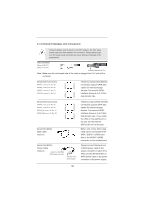
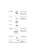
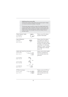
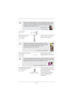
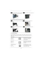
3.5mm Audio Cable (Optional) USB 2.0 Headers (9-pin USB6_7) (see p.13 No. 30) (9-pin USB8_9) (see p.13 No. 29) (9-pin USB10_11) (see p.13 No. 28) USB 3.0 Header (19-pin USB3_12_13) (see p.13 No. 26) USB_PWR P-9 P+9 GND DUMMY 1 GND P+8 P-8 USB_PWR USB_PWR P-11 P+11 GND DUMMY 1 GND P+10 P-10 USB_PWR IntA_P2_D+ IntA_P2_DGND IntA_P2_SSTX+ IntA_P2_SSTXGND IntA_P2_SSRX+ IntA_P2_SSRXVbus 1 Vbus IntA_P1_SSRXIntA_P1_SSRX+ GND IntA_P1_SSTXIntA_P1_SSTX+ GND IntA_P1_DIntA_P1_D+ ID Infrared Module Header (5-pin IR1) (see p.13 No. 33) IRTX +5VSB DUMMY 1 GND IRRX Consumer Infrared Module Header (4-pin CIR1) (see p.13 No. 31) 1 GND IRTX IRRX ATX+5VSB Either end of the 3.5mm audio cable can be connected to the portable audio devices, such as MP3 player and mobile phone or the Line-in port of your PC. Besides four default USB 2.0 ports on the I/O panel, there are three USB 2.0 headers on this motherboard. Each USB 2.0 header can support two USB 2.0 ports. Besides two default USB 3.0 ports on the I/O panel, there is one USB 3.0 header on this motherboard. This USB 3.0 header can support two USB 3.0 ports. This header supports an optional wireless transmitting and receiving infrared module. This header can be used to connect the remote controller receiver. 39
-
 1
1 -
2
-
3
-
4
-
5
-
6
-
7
-
8
-
9
-
10
-
11
-
12
-
13
-
14
-
15
-
16
-
17
-
18
-
19
-
20
-
21
-
22
-
23
-
24
-
25
-
26
-
27
-
28
-
29
-
30
-
31
-
32
-
33
-
 34
34 -
 35
35 -
 36
36 -
 37
37 -
 38
38 -
 39
39 -
 40
40 -
 41
41 -
 42
42 -
 43
43 -
 44
44 -
45
-
46
-
47
-
48
-
49
-
50
-
51
-
52
-
53
-
54
-
55
-
56
-
57
-
58
-
59
-
60
-
61
-
62
-
63
-
64
-
65
-
66
-
67
-
68
-
69
-
70
-
71
-
72
-
73
-
74
-
75
-
76
-
77
-
78
-
79
-
80
-
81
 |
 |
