Airlink APO1000 Quick Installation Guide - Page 3
System Overview
 |
View all Airlink APO1000 manuals
Add to My Manuals
Save this manual to your list of manuals |
Page 3 highlights
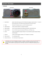
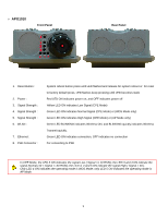
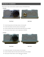
System Overview ¾ APO1000 Front Panel Rear Panel 1. Reset Button : System reboot button press until LED flashed and release for system reboot or for reset to factory default press, LED flashes keep pressing until LED becomes static 2. Power : Red LED ON indicates power on, and OFF indicates power off 3. Signal Strength : Yellow LED ON indicates Low Signal (CPE Mode) 4. Signal Strength : Green LED ON indicates Normal Signal (CPE Mode) or (WDS Mode only) 5. Signal Strength : Green LED ON indicates High Signal (CPE Mode) or (AP Mode only) 6. WLAN : Green LED BLINKING indicates Wireless ON, and BLINKING quickly indicates Wireless Transmit quickly. 7. Ethernet : Green LED ON indicates connection, OFF indicates no connection 8. PoE Connector : For connecting to PSE 9. N-Type Connector : For connecting to N-Type antenna In CPE Mode, the LED 3 ON indicates the signal Low ( Signal
-
 1
1 -
 2
2 -
 3
3 -
 4
4 -
 5
5 -
 6
6 -
 7
7 -
 8
8 -
 9
9 -
10
-
11
-
12
-
13
-
14
-
15
-
16
-
17
-
18
-
19
-
20
-
21
-
22
-
23
 |
 |
