Airlink APO1000 Quick Installation Guide - Page 5
Hardware Installation
 |
View all Airlink APO1000 manuals
Add to My Manuals
Save this manual to your list of manuals |
Page 5 highlights
Hardware Installation Please follow the steps mentioned below to install the hardware of APO1000/APO1010 : ¾ APO1000 Front Panel Rear Panel Î Connect N-type antenna to the N-type connector on the rear panel. Î Connect Power Injector to the PoE connector on the front panel. Î Connect an Ethernet cable to the Power Injector and the other end to a computer. Î Source power to Power Injector in order to supply power to APO1000 ¾ APO1010 Front Panel Rear Panel Î Connect Power Injector to the PoE connector on the front panel. Î Connect an Ethernet cable to the Power Injector and the other end to a computer. Î Source power to Power Injector in order to supply power to APO1010 4
-
 1
1 -
 2
2 -
 3
3 -
 4
4 -
 5
5 -
 6
6 -
 7
7 -
 8
8 -
 9
9 -
 10
10 -
 11
11 -
12
-
13
-
14
-
15
-
16
-
17
-
18
-
19
-
20
-
21
-
22
-
23
 |
 |

4
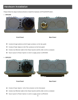
Please follow the steps mentioned below to install the hardware of APO1000/APO1010 :
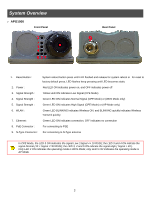
APO1000
Front Panel
Rear Panel
Connect N-type antenna to the N-type connector on the rear panel.
Connect Power Injector to the PoE connector on the front panel.
Connect an Ethernet cable to the Power Injector and the other end to a computer.
Source power to Power Injector in order to supply power to APO1000
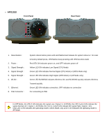
APO1010
Front Panel
Rear Panel
Connect Power Injector
to the PoE connector on the front panel.
Connect an Ethernet cable to the Power Injector and the other end to a computer.
Source power to Power Injector in order to supply power to APO1010
Hardware Installation