Airlink APSUSB2 Manual - Page 7
Network Cable Connector, DC Power Connector, LED Indicators - () print server
 |
View all Airlink APSUSB2 manuals
Add to My Manuals
Save this manual to your list of manuals |
Page 7 highlights
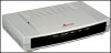
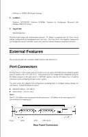
Network Cable Connector The Print Server's rear panel features an RJ-45 connector for connection to 10Base-T Ethernet cabling or 100Base-TX Fast Ethernet cabling (which should be Category 5 twisted-pair cable). The port supports the NWay protocol, allowing the print server to automatically detect or negotiate the transmission speed of the network. DC Power Connector The DC power input connector is located on the Print Server's rear panel and is labeled DC 5V LED Indicators The front panel of the Print Server features five LED indicators: Power LPT2 Link/Act USB LPT1 Front Panel LED Indicators ♦ Power ◊ Steady or flashing green confirms that the Print Server is powered on. ♦ Link/Act ◊ Steady or flashing green confirms that the Print Server has a good connection to the Ethernet or Fast Ethernet network. ◊ The indicator blinks off briefly to indicate that the Print Server is receiving or transmitting from the network. ♦ USB, LPT1 , LPT2 ◊ These LED indicators light to show that the Print Server is transferring print data through the appropriate parallel port or USB port. These three indicators are also used by the print server's power-on self test (POST) to indicate any hardware failures.
-
 1
1 -
 2
2 -
 3
3 -
 4
4 -
 5
5 -
 6
6 -
 7
7 -
 8
8 -
 9
9 -
 10
10 -
 11
11 -
 12
12 -
13
 |
 |
