Alpine MRX-V60 Owner's Manual (english, French, Espanol)
Alpine MRX-V60 Manual
 |
UPC - 793276301079
View all Alpine MRX-V60 manuals
Add to My Manuals
Save this manual to your list of manuals |
Alpine MRX-V60 manual content summary:
- Alpine MRX-V60 | Owner's Manual (english, French, Espanol) - Page 1
FOR CAR USE ONLY/POUR APPLICATION AUTOMOBILE/PARA USO EN AUTOMÓVILES MRX-V60 4 CHANNEL + MONO POWER AMPLIFIER MRX-F30 4 CHANNEL POWER AMPLIFIER • OWNER'S MANUAL Please read this manual to maximize your enjoyment of the outstanding performance and feature capabilities of the equipment, then retain - Alpine MRX-V60 | Owner's Manual (english, French, Espanol) - Page 2
enjoyment. In case of problems when installing your MRX-V60/MRX-F30, please contact your authorized ALPINE dealer. CAUTION: These controls are for tuning your system. Please consult your authorized Dealer for adjustment. WARNING CAUTION This symbol means important instructions. Failure to heed - Alpine MRX-V60 | Owner's Manual (english, French, Espanol) - Page 3
HALT USE IMMEDIATELY IF A PROBLEM APPEARS. Failure to do so may cause personal injury or damage to the product. Return it to your authorized Alpine dealer or the nearest Alpine Service Center for repairing. HAVE THE WIRING AND INSTALLATION DONE BY EXPERTS. The wiring and installation of this unit - Alpine MRX-V60 | Owner's Manual (english, French, Espanol) - Page 4
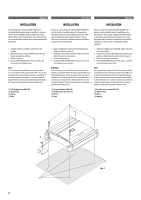
INSTALLATION Due to the high power output of the MRX-V60/MRX-F30, considerable heat is produced when the amplifier is in operation. For this reason, the amplifier différentes positions d'installation, contacter un concessionnaire Alpine. Debido a la salida de alta potencia del MRX-V60/MRX-F30, se - Alpine MRX-V60 | Owner's Manual (english, French, Espanol) - Page 5
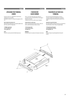
English Français Español ATTACHING THE TERMINAL COVERS Attach the terminal covers (supplied) after connections and confirmation of correct operation. Attaching the terminal covers will improve the appearance of the unit. How to attach the terminal covers: Attach the left and right terminal covers - Alpine MRX-V60 | Owner's Manual (english, French, Espanol) - Page 6
grease if necessary) of the car chassis. • If you add an optional noise suppressor, connect it as far away from the unit as possible. Your Alpine dealer carries various noise suppressors, contact them for further information. • Your Alpine dealer knows best about noise prevention measures so consult - Alpine MRX-V60 | Owner's Manual (english, French, Espanol) - Page 7
the left and right channels. Do not connect this MRX-V60 30A x2 • MRX-F30 25A x2 UTILICE EL AMPERAJE CORRECTO CUANDO CAMBIE FUSIBLES. De lo contrario, puede producirse un incendio o una descarga eléctrica. c Power wire gauge requirement. MRX-V60 60 amp fuse, 4AWG/21mm2 MRX-F30 50 amp car le - Alpine MRX-V60 | Owner's Manual (english, French, Espanol) - Page 8
, you should connect these wires to the speaker output leads of your head unit. The MRX-V60/MRX-F30 accepts input from high power or standard power head units. NOTES: • If connecting the Speaker Input Leads and RCA Inputs at the same time, be sure to connect to different Input channels. Refer to the - Alpine MRX-V60 | Owner's Manual (english, French, Espanol) - Page 9
one amplifier, a distribution block should be used. See below for wire gauge recommendations for distribution block connection to battery and ground (depends upon wire length necessary): MRX-V60 2AWG (33mm2) or 1/0AWG (53mm2) MRX-F30 4AWG (21mm2) or 2AWG (33mm2) Ensure that you install a correctly - Alpine MRX-V60 | Owner's Manual (english, French, Espanol) - Page 10
be installed in-line on the MRX-V60/MRX-F30 turn-on lead. This switch will then be used to turn on (and off) the MRX-V60/ MRX-F30. Therefore, the switch should be mounted so that is accessible by the driver. Make sure the switch is turned off when the vehicle is not running. Otherwise, the amplifier - Alpine MRX-V60 | Owner's Manual (english, French, Espanol) - Page 11
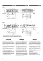
Channel Selector Switch (MRX-V60 only) a) This switch setting is for selecting either 2-channel for 4-channel canaux. s Interruptor de selector de canal de entrada (sólo MRXV60) a) Este ajuste de cambio sirve para seleccionar el modo (MRX-V60 Only) a) Set to the "OFF" position when the amplifier - Alpine MRX-V60 | Owner's Manual (english, French, Espanol) - Page 12
del MRX-V60. x Subsonic Filter (MRX-V60 only) The subsonic filter is for cutting ultra low frequencies from the input signal before being amplified. This is desirable for several reasons: - To protect speakers too small or not capable of reproducing ultra low frequencies. - To minimize power wasted - Alpine MRX-V60 | Owner's Manual (english, French, Espanol) - Page 13
DU SYSTÈME/DIAGRAMAS DEL SISTEMA • TYPICAL SYSTEM CONNECTIONS/CONNEXIONS TYPIQUES DU SYSTÈME/CONEXIONES TÍPICAS DEL SISTEMA MRX-V60 Input Channel Selector Switch/Commutateur sélecteur du canal d'entrée/Interruptor de selector de canal de entrada · · · 3/4 · · · SUB.W 8 L R 9 L R 30 30 25 - Alpine MRX-V60 | Owner's Manual (english, French, Espanol) - Page 14
• Bridged Connections/Connexions pontées/Conexiones puenteadas MRX-V60 Input Channel Selector Switch/Commutateur sélecteur du canal d'entrée/Interruptor de selector de canal de entrada · · · 1/2 · · · 1+2+3+4 8 L R 30 30 MRX-F30 (Left side/ Côté gauche/ Lado izquierdo) 0 df 8 L R ( - Alpine MRX-V60 | Owner's Manual (english, French, Espanol) - Page 15
cuando conecte en puente un amplificador NOTE: Low output will result if only one channel input is used. The Y-adapter is not required if a stereo/mono pair line output is used to drive both inputs of the bridged amp. REMARQUE : Le système présente une faible puissance en cas d'utilisation d'un - Alpine MRX-V60 | Owner's Manual (english, French, Espanol) - Page 16
une entrée à 2 canaux/Ejemplo de sistema de entrada de 2 canales MRX-V60 Input Channel Selector Switch/Commutateur sélecteur du canal d'entrée/Interruptor de selector de canal de entrada • This switch setting also applies for 2-channel input using Speaker Level Input Leads./Ce réglage du commutateur - Alpine MRX-V60 | Owner's Manual (english, French, Espanol) - Page 17
ème type)/Sistema de entrada de nivel de altavoz (Sistema estándar) MRX-V60 Input Channel Selector Switch/Commutateur sélecteur du canal d'entrée/Interruptor de selector de canal connect the Remote Turn-On Lead to an incoming power supply cord (accessory power) in the ACC position. ★2 If connecting - Alpine MRX-V60 | Owner's Manual (english, French, Espanol) - Page 18
/Ejemplo de sistema con conexiones de nivel de altavoz y de entrada RCA MRX-V60 Input Channel Selector Switch/Commutateur sélecteur du canal d'entrée/Interruptor de selector de canal the Remote Turn-On Lead to an incoming power supply cord (accessory power) in the ACC position. ★2 If connecting - Alpine MRX-V60 | Owner's Manual (english, French, Espanol) - Page 19
English Français Español SPECIFICATIONS MRX-F30 MRX-V60 CH1/2/3/4 Sub W. Power Output Per Channel, Ref: 14.4V, 4 ohms 50W RMS 50W RMS 200W x 4 x 4 RMS x 1 Per Channel, Ref: 14.4V, 2 ohms 75W RMS 75W RMS 300W x 4 x 4 RMS x 1 Breged, Ref: 14.4V, 150W 150W - 4 ohms RMS x 2 RMS x 2 - Alpine MRX-V60 | Owner's Manual (english, French, Espanol) - Page 20
SERVICE CARE ♦ IMPORTANT NOTICE This Amplifier has been type tested and found to comply with the limits for a Class B computing device in accordance with the specifications in Subpart J of Part 15 of FCC Rules. This equipment generates and uses radio frequency energy, and it must be installed and
-
 1
1 -
 2
2 -
 3
3 -
 4
4 -
 5
5 -
 6
6 -
 7
7 -
8
-
9
-
10
-
11
-
12
-
13
-
14
-
15
-
16
-
17
-
18
-
19
-
20
 |
 |

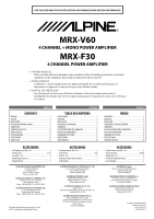
OWNER’S MANUAL
Please read this manual to maximize your enjoyment of the outstanding performance and feature
capabilities of the equipment, then retain the manual for future reference.
MODE D’EMPLOI
Veuillez lire ce mode d’emploi pour tirer pleinement profit des excellentes performances et
fonctions de cet appareil, et conservez-le pour toute référence future.
MANUAL DE OPERACIÓN
Lea este manual, por favor, para disfrutar al máximo de las excepcionales prestaciones y
posibilidades funcionales que ofrece el equipo, luego guarde el manual para usarlo como referencia
en el futuro.
•
•
•
FOR CAR USE ONLY/POUR APPLICATION AUTOMOBILE/PARA USO EN AUTOMÓVILES
MRX-V60
4 CHANNEL + MONO POWER AMPLIFIER
MRX-F30
4 CHANNEL POWER AMPLIFIER
English
Français
Español
CONTENTS
WARNING
.................................................................................
2
CAUTION
...................................................................................
3
INSTALLATION
..........................................................................
4
ATTACHING THE TERMINAL COVERS
...........................................
5
CONNECTIONS
..........................................................................
6
CONNECTION CHECK LIST
........................................................
10
SWITCH SETTINGS
...................................................................
11
SYSTEM DIAGRAMS
................................................................
13
SPECIFICATIONS
......................................................................
19
SERVICE CARE
.........................................................................
20
TABLE DES MATIÈRES
AVERTISSEMENT
.......................................................................
2
ATTENTION
...............................................................................
3
INSTALLATION
..........................................................................
4
FIXATION DES CACHE-BORNES
..................................................
5
CONNEXIONS
............................................................................
6
LISTE DE VÉRIFICATION DES CONNEXIONS
...............................
10
RÉGLAGES DE COMMUTATEUR
................................................
11
DIAGRAMMES DU SYSTÈME
....................................................
13
SPÉCIFICATIONS
......................................................................
19
SOINS PRATIQUES
...................................................................
20
ÍNDICE
ADVERTENCIA
...........................................................................
2
PRUDENCIA
..............................................................................
3
INSTALACIÓN
............................................................................
4
FIJACIÓN DE LAS TAPAS DEL TERMINAL
.....................................
5
CONEXIONES
.............................................................................
6
LISTA DE COMPROBACIÓN DE CONEXIONES
.............................
10
AJUSTES DEL INTERRUPTOR
....................................................
11
DIAGRAMAS DEL SISTEMA
......................................................
13
ESPECIFICACIONES
..................................................................
19
CUIDADOS PRÁCTICOS
............................................................
20
ACCESSORIES
Self-Tapping Screw (M4 × 20)
..............................................
4
Terminal Cover
................................................................
1 SET
Screw (M3 × 10)
..................................................................
4
Speaker Input Connector
......................................................
1
Hexagon Wrench
..................................................................
1
•
•
•
•
•
ACCESSOIRES
Vis autotaraudeuse (M4 × 20)
..............................................
4
Cache-bornes
.................................................................
1 JEU
Vis (M3 × 10)
.......................................................................
4
Connecteur d’entrée de haut-parleur
....................................
1
Clé hexagonale
.....................................................................
1
•
•
•
•
•
ACCESORIOS
Tornillo autorroscante (M4 × 20)
.........................................
4
Tapa del terminal
.......................................................
1 JUEGO
Tornillo (M3 × 10)
................................................................
4
Conector de entrada del altavoz
...........................................
1
Llave hexagonal
...................................................................
1
•
•
•
•
•
ALPINE ELECTRONICS MARKETING, INC.
1-1-8 Nishi Gotanda,
Shinagawa-ku,
Tokyo 141-0031, Japan
Phone
03-5496-8231
ALPINE ELECTRONICS OF AMERICA, INC.
19145 Gramercy Place, Torrance,
California 90501, U.S.A.
Phone 1-800-ALPINE-1 (1-800-257-4631)
ALPINE ELECTRONICS OF CANADA, INC.
777 Supertest Road, Toronto,
Ontario M3J 2M9, Canada
Phone 1-800-ALPINE-1 (1-800-257-4631)
ALPINE ELECTRONICS OF AUSTRALIA PTY. LTD.
161-165 Princes Highway, Hallam
Victoria 3803, Australia
Phone 03-8787-1200
ALPINE ELECTRONICS GmbH
Wilhelm-Wagenfeld-Str. 1-3,
80807 München, Germany
Phone 089-32 42 640
ALPINE ELECTRONICS OF U.K. LTD.
Alpine House
Fletchamstead Highway, Coventry CV4 9TW,
U.K.
Phone 0870-33 33 763
ALPINE ELECTRONICS FRANCE S.A.R.L.
(RCS PONTOISE B 338 101 280)
98, Rue de la Belle Etoile, Z.I. Paris Nord Il,
B.P. 50016, 95945 Roissy Charles de Gaulle
Cedex, France
Phone 01-48638989
ALPINE ITALIA S.p.A.
Viale C. Colombo 8, 20090 Trezzano
Sul Naviglio (MI), Italy
Phone 02-484781
ALPINE ELECTRONICS DE ESPAÑA, S.A.
Portal de Gamarra 36, Pabellón, 32
01013 Vitoria (Alava)-APDO 133, Spain
Phone 945-283588
ALPINE ELECTRONICS (BENELUX) GmbH
Leuvensesteenweg 510-B6,
1930 Zaventem, Belgium
Phone 02-725-13 15
Qingdao Dongli Xinhaiyuan Printing Co., Ltd.
No.17, jiushuidong road,Qingdao, China
Designed by ALPINE Japan
Printed in China (Y)
68-13530Z75-A
M3514433010