Asus A8V-E SE A8V-E SE User's Manual for English Edition
Asus A8V-E SE Manual
 |
View all Asus A8V-E SE manuals
Add to My Manuals
Save this manual to your list of manuals |
Asus A8V-E SE manual content summary:
- Asus A8V-E SE | A8V-E SE User's Manual for English Edition - Page 1
A8V-E SE Motherboard - Asus A8V-E SE | A8V-E SE User's Manual for English Edition - Page 2
express written permission of ASUSTeK COMPUTER INC. ("ASUS"). Product warranty or service will not be extended if: (1) the ASUS HAS BEEN ADVISED OF THE POSSIBILITY OF SUCH DAMAGES ARISING FROM ANY DEFECT OR ERROR IN THIS MANUAL OR PRODUCT. SPECIFICATIONS AND INFORMATION CONTAINED IN THIS MANUAL - Asus A8V-E SE | A8V-E SE User's Manual for English Edition - Page 3
used in this guide ix Typography ix A8V-E SE specifications summary x Chapter 1: Product introduction 1.1 Welcome 1-2 1.2 Package contents 1-2 1.3 Special features 1-3 1.3.1 Product highlights 1-3 1.3.2 Innovative ASUS features 1-5 1.4 Before you proceed 1-6 1.5 Motherboard overview - Asus A8V-E SE | A8V-E SE User's Manual for English Edition - Page 4
CrashFree BIOS 2 utility 2-6 2.1.5 ASUS EZ Flash utility 2-8 2.1.6 ASUS Update utility 2-9 2.2 BIOS setup program 2-12 2.2.1 BIOS menu screen 2-13 2.2.2 Menu bar 2-13 2.2.3 Legend bar 2-14 2.2.4 Menu items 2-14 2.2.5 Sub-menu items 2-14 2.2.6 Configuration fields 2-14 2.2.7 Pop-up window - Asus A8V-E SE | A8V-E SE User's Manual for English Edition - Page 5
Drives 2-35 2.6.5 Boot Settings Configuration 2-35 2.6.6 Security 2-37 2.7 Exit menu 2-38 Chapter 3: Software support 3.1 Installing an operating system 3-2 3.2 Support CD information 3-2 3.2.1 Running the support CD 3-2 3.2.2 Drivers menu 3-3 3.2.3 Utilities menu 3-4 3.2.4 ASUS Contact - Asus A8V-E SE | A8V-E SE User's Manual for English Edition - Page 6
. This equipment generates, uses and can radiate radio frequency energy and, if not installed and used in accordance with manufacturer's instructions, may cause harmful interference to radio communications. However, there is no guarantee that interference will not occur in a particular installation - Asus A8V-E SE | A8V-E SE User's Manual for English Edition - Page 7
are using, contact your local power company. • If the power supply is broken, do not try to fix it by yourself. Contact a qualified service technician or your retailer. Operation safety • Before installing the motherboard and adding devices on it, carefully read all the manuals that came with the - Asus A8V-E SE | A8V-E SE User's Manual for English Edition - Page 8
the BIOS parameters are also provided. • Chapter 3: Software support This chapter describes the contents of the support CD that comes with the motherboard package. Where to find more information Refer to the following sources for additional information and for product and software updates. 1. ASUS - Asus A8V-E SE | A8V-E SE User's Manual for English Edition - Page 9
following symbols used throughout this manual. D A N G E R / W A R N I N G : Information to prevent injury to yourself when trying to complete a task. C A U T I O N : Information to prevent damage to the components when trying to complete a task. I M P O R T A N T : Instructions that you MUST follow - Asus A8V-E SE | A8V-E SE User's Manual for English Edition - Page 10
A8V-E SE specifications summary CPU Socket 939 for AMD Athlon™ 64/AMD Athlon™ 64FX/ AMD Athlon™ 64 X2 processor Supports AMD 64 architecture that enables simultaneous 32-bit and 64-bit architecture Supports AMD Cool 'n' Quiet! Technology Chipset Northbridge: VIA® K8T890 Southbridge: VIA® VT8237R - Asus A8V-E SE | A8V-E SE User's Manual for English Edition - Page 11
A8V-E SE specifications summary BIOS features Rear panel Internal connectors Power Requirement Form Factor Support CD contents 4 MB Flash ROM, Award BIOS, PnP, DMI2.0, WfM2.0, SM BIOS 2.3 1 x Parallel port 1 x LAN (RJ-45) port 4 x USB 2.0 ports 1 x Coaxial S/PDIF out port 1 x PS/2 keyboard port 1 - Asus A8V-E SE | A8V-E SE User's Manual for English Edition - Page 12
xii - Asus A8V-E SE | A8V-E SE User's Manual for English Edition - Page 13
This chapter describes the motherboard features and the new technologies it supports. 1Product introduction ASUS A8V-E SE 1-1 - Asus A8V-E SE | A8V-E SE User's Manual for English Edition - Page 14
ASUS A8V-E SE motherboard Cables 2 x Serial ATA signal cables 2 x Serial ATA power cables 1 x Ultra DMA/133 cables 1 x 40-conductor IDE cable 1 x Floppy disk drive cable Accessories I/O shield A p p l i c a t i o n C D s ASUS motherboard support CD D o c u m e n t a t i o n User guide - Asus A8V-E SE | A8V-E SE User's Manual for English Edition - Page 15
the Double Data Rate (DDR) memory technology, the motherboard supports up to 4GB of system memory using DDR400/333/ 266 DIMMs. The ultra-fast 400MHz memory bus delivers the required bandwidth for the latest 3D graphics, multimedia, and Internet applications. See page 1-13. ASUS A8V-E SE 1-3 - Asus A8V-E SE | A8V-E SE User's Manual for English Edition - Page 16
with existing PCI specifications. See page 1-19 for details. AI Audio technology The motherboard supports 8-channel audio through the onboard powerful audio and speaker systems. See page 1-23 for details. USB 2.0 technology The motherboard implements the Universal Serial Bus (USB) 2.0 specification - Asus A8V-E SE | A8V-E SE User's Manual for English Edition - Page 17
This feature allows you to restore the original BIOS data from the support CD in case when the BIOS codes and data are corrupted. This protection eliminates the need to buy a replacement ROM chip. See details on page 2-6. ASUS Q-Fan technology The ASUS Q-Fan technology smartly adjusts the fan speeds - Asus A8V-E SE | A8V-E SE User's Manual for English Edition - Page 18
before you install motherboard components or change any motherboard settings. • Unplug the power cord from the wall socket before touching any unplug the power cable before removing or plugging in any motherboard component. A8V-E SE ® A8V-E SE Onboard LED SB_PWR ON Standby Power OFF Powered Off - Asus A8V-E SE | A8V-E SE User's Manual for English Edition - Page 19
as indicated in the image below. 1.5.2 Screw holes Place nine (9) screws into the holes indicated by circles to secure the motherboard to the chassis. Do not overtighten the screws! Doing so can damage the motherboard. Place this side towards the rear of the chassis A8V-E SE ® ASUS A8V-E SE 1-7 - Asus A8V-E SE | A8V-E SE User's Manual for English Edition - Page 20
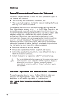
bit,184-pin module) PARALLEL PORT SPDIF_O Socket 939 USB12 LAN_USB34 Top:Rear Speaker Out Center: Side Speaker Out Below: Center/Subwoofer Top:Line In Center:Line Out Bottom:Mic In ATX12V Marvell 88E8053 VIA K8T890 PCIEX1_1 PWR_FAN A8V-E SE CHA_FAN PCIEX16 PCIEX1_2 FP_AUDIO AUX ALC850 - Asus A8V-E SE | A8V-E SE User's Manual for English Edition - Page 21
This mark should match a specific corner on the socket to ensure correct installation. Gold triangle 1.6.2 Installling the CPU To install a CPU: 1. Locate the CPU socket on the motherboard. A8V-E SE ® A8V-E SE CPU Socket 939 Before installing the CPU, make sure that the socket box is facing towards - Asus A8V-E SE | A8V-E SE User's Manual for English Edition - Page 22
fits in place. Small triangle Gold triangle The CPU fits only in one correct orientation. DO NOT force the CPU into the socket to prevent bending the pins and damaging the CPU! 5. When the CPU is in place, push down the socket lever to secure the CPU. The lever clicks on the side tab to indicate - Asus A8V-E SE | A8V-E SE User's Manual for English Edition - Page 23
or AMD Athlon™ 64 X2 processors require a specially designed heatsink CPU heatsink and fan assembly should come with installation instructions for the CPU, heatsink, and the retention mechanism. If the instructions in this section do not match the CPU documentation, follow the latter. ASUS A8V-E SE - Asus A8V-E SE | A8V-E SE User's Manual for English Edition - Page 24
When the fan and heatsink assembly is in place, connect the CPU fan cable to the connector on the motherboard labeled CPU_FAN. CPU_FAN Rotation +12V GND A8V-E SE ® A8V-E SE CPU Fan connector Do not forget to connect the CPU fan connector! Hardware monitoring errors can occur if you fail to plug - Asus A8V-E SE | A8V-E SE User's Manual for English Edition - Page 25
recommended that you obtain memory memory modules. • Due to chipset limitation, DIMM modules with 128 Mb memory chips or double-sided x16 memory chips are not supported in this motherboard. • Due to CPU limitation, install on Channel B slots for a single-channel memory configuration. ASUS A8V-E SE - Asus A8V-E SE | A8V-E SE User's Manual for English Edition - Page 26
Table 1 Recommended memory configurations Mode Single-channel Dual-channel* Sockets DIMM_A1 DIMM_A2 DIMM_B1 DIMM_B2 (1) - - Populated - (1) Populated - Populated - (2) Populated Populated Populated Populated * Use only identical DDR DIMM pairs. * For dual-channel configuration (3), you - Asus A8V-E SE | A8V-E SE User's Manual for English Edition - Page 27
NANYA NT512D64S8HC0G-5T BRAIN POWER B6U808-256M-SAM-400 memory configuration. C - support for 4 modules inserted into the yellow and black slots as two pairs of Dual-channel memory configuration. Visit the ASUS website (www.asus.com) for the latest DDR400 Qualified Vendors List. ASUS A8V-E SE - Asus A8V-E SE | A8V-E SE User's Manual for English Edition - Page 28
1.7.3 Installing a DIMM Make sure to unplug the power supply before adding or removing DIMMs or other system components. Failure to do so may cause severe damage to both the motherboard and the components. 1. Unlock a DIMM socket by pressing the retaining clips outward. 2. Align a DIMM on the - Asus A8V-E SE | A8V-E SE User's Manual for English Edition - Page 29
the slots and the expansion cards that they support. Make sure to unplug the power cord before adding or removing expansion cards. Failure to do so may cause you physical injury and damage motherboard components. We recommended to install the memory modules first before installing a PCI Express x16 - Asus A8V-E SE | A8V-E SE User's Manual for English Edition - Page 30
motherboard PCI slot 1 PCI slot 2 PCI slot 3 PCI E x1 slot 1 PCI E x1 slot 2 PCI E x16 slot Onboard USB controller 1 Onboard USB controller 2 Onboard USB controller 3 Onboard USB controller 4 Onboard USB 2.0 controller Onboard LAN shared slots, ensure that the drivers support "Share IRQ" or that the - Asus A8V-E SE | A8V-E SE User's Manual for English Edition - Page 31
graphics card installed on the PCI Express x16 slot. 1.8.6 PCI Express x1 slot This motherboard supports PCI Express x1 network cards, SCSI cards and other cards that comply with the PCI Express specifications. The figure shows a network card installed on the PCI Express x1 slot. ASUS A8V-E SE 1-19 - Asus A8V-E SE | A8V-E SE User's Manual for English Edition - Page 32
failure! A8V-E SE ® A8V-E SE Clear RTC RAM CLRTC 12 23 Normal (Default) Clear CMOS You do not need to clear the RTC when the system hangs due to overclocking. For system failure due to overclocking, use the C.P.R. (CPU Parameter Recall) feature. Shut down and reboot the system so the BIOS can - Asus A8V-E SE | A8V-E SE User's Manual for English Edition - Page 33
key on the keyboard (the default is the Space Bar). This feature requires an ATX power supply that can supply at least 1A on the +5VSB lead, and a corresponding setting in the BIOS. A8V-E SE KBPWR 2 1 +5V (Default) 2 1 +5VSB ® A8V-E SE Keyboard power setting ASUS A8V-E SE 1-21 Refer of the - Asus A8V-E SE | A8V-E SE User's Manual for English Edition - Page 34
scanner, or other devices. 2 . L A N R J - 4 5 p o r t . This port allows Gigabit connection to a Local Area Network (LAN) through a network hub. Refer to the table below for the LAN port LED indications. LAN port LED indications ACT/LINK LED Status OFF GREEN BLINKING Description No link Linked - Asus A8V-E SE | A8V-E SE User's Manual for English Edition - Page 35
the floppy disk drive. The Pin 5 on the connector is removed to prevent incorrect cable connection when using an FDD cable with a covered Pin 5. A8V-E DELUXE ® FLOPPY NOTE: Orient the red markings on the floppy ribbon cable to PIN 1. PIN 1 A8V-E SE Floppy disk drive connector ASUS A8V-E SE 1-23 - Asus A8V-E SE | A8V-E SE User's Manual for English Edition - Page 36
primary IDE connector on the motherboard, a black connector for an Ultra DMA 133/100/66 IDE slave device (optical drive/hard disk drive), and a gray connector IDE cable for UltraDMA133/100/66 IDE devices. SEC_IDE PRI_IDE A8V-E SE ® A8V-E SE IDE connectors PIN 1 NOTE: Orient the red markings ( - Asus A8V-E SE | A8V-E SE User's Manual for English Edition - Page 37
RSATA_TXN1 GND RSATA_RXP1 RSATA_RXN1 GND A8V-E SE SATA connectors Important notes on Serial ATA • The Serial ATA RAID feature (RAID 0, RAID 1 and JBOD) is available only if you are using Windows® 2000/XP. • Install the Windows® 2000 Service Pack 4 or the Windows® XP Service Pack1 when using Serial - Asus A8V-E SE | A8V-E SE User's Manual for English Edition - Page 38
inside the system may damage the motherboard components. These are not jumpers! DO NOT place jumper caps on the fan connectors! CPU_FAN Rotation +12V GND Rotation +12V GND A8V-E SE ® A8V-E SE Fan connectors PWR_FAN CHA_FAN Rotation +12V GND 6 . Internal audio connectors (4-pin CD, AUX) These - Asus A8V-E SE | A8V-E SE User's Manual for English Edition - Page 39
USB 2.0 specification that supports up to 480 Mbps connection speed. Never connect a 1 3 9 4 c a b l e to the USB connectors. Doing so will damage the motherboard! USB+5V USB_P8USB_P8+ GND NC USB+5V USB_P6USB_P6+ GND NC USB+5V USB_P7USB_P7+ GND A8V-E SE ® USB56 1 A8V-E SE USB 2.0 connectors - Asus A8V-E SE | A8V-E SE User's Manual for English Edition - Page 40
if you intend to install additional devices. EATXPWR +3 Volts -12 Volts ATX12V Ground PSON# A8V-E SE GND +12V DC GND Ground +12V DC Ground Ground -5 Volts ® +5 Volts +5 Volts A8V-E SE ATX power connectors +5 Volts Ground +3 Volts +3 Volts Ground +5 Volts Ground +5 Volts Ground - Asus A8V-E SE | A8V-E SE User's Manual for English Edition - Page 41
for playing games, and MIDI devices for playing or editing audio files. +5V J2B1 J2CX MIDI_OUT J2CY J2B2 MIDI_IN A8V-E SE ® A8V-E SE Game connector GAME +5V J1B1 J1CX GND GND feature. +5VSB_MB Chassis Signal GND A8V-E SE CHASSIS ® (Default) A8V-E SE Chassis alarm lead ASUS A8V-E SE 1-29 - Asus A8V-E SE | A8V-E SE User's Manual for English Edition - Page 42
-pin PANEL) This connector supports several chassis-mounted functions. PLED SPEAKER PLED+ PLED+5V Ground Ground Speaker A8V-E SE PANEL IDE_LED+ IDE_LED- ExtSMI# Ground PWR Ground Reset Ground IDE LED RESET ® SMI PWR * Requires an ATX power supply. A8V-E SE System panel connector The sytem - Asus A8V-E SE | A8V-E SE User's Manual for English Edition - Page 43
This chapter tells how to change the system settings through the BIOS Setup menus. Detailed descriptions of the BIOS parameters are also provided. 2 BIOS setup ASUS A8V-E SE 2-1 - Asus A8V-E SE | A8V-E SE User's Manual for English Edition - Page 44
using a bootable floppy disk or the motherboard support CD when the BIOS file fails or gets corrupted.) 3. A S U S E Z F l a s h (Updates the BIOS in DOS using a floppy disk or the motherboard support CD.) 4. A S U S U p d a t e (Updates the BIOS in Windows® environment.) Refer to the corresponding - Asus A8V-E SE | A8V-E SE User's Manual for English Edition - Page 45
or the latest motherboard BIOS file to the bootable floppy disk. 2.1.2 Updating the BIOS The Basic Input/Output System (BIOS) can be updated using the AwardBIOS Flash Utility. Follow these instructions to update the BIOS using this utility. 1. Download the latest BIOS file from the ASUS web site - Asus A8V-E SE | A8V-E SE User's Manual for English Edition - Page 46
file. The following screen appears. 8. The utility verifies the BIOS file in the floppy disk and starts flashing the BIOS file. AwardBIOS Flash Utility for ASUS V1.01 (C) Phoenix Technologies Ltd. All Rights Reserved For K8T890-8237-A8V-E-00 DATE: 09/10/2004 Flash Type - PMC Pm49FL004T LPC/FWH - Asus A8V-E SE | A8V-E SE User's Manual for English Edition - Page 47
Rights Reserved For K8T890-8237-A8V-E-00 DATE: 09/10/2004 Flash Type - PMC Pm49FL004T LPC/FWH File Name to Program: A8V-E_SE.BIN Now Backup System BIOS to 111222333444555666777888999000111222333444555666777888999000111222333F444i555666l777e888!999000111 Message: Please Wait! ASUS A8V-E SE 2-5 - Asus A8V-E SE | A8V-E SE User's Manual for English Edition - Page 48
BIOS file. Prepare the motherboard support CD or the floppy disk containing the updated motherboard BIOS before using this utility. Recovering the BIOS from the support CD To recover the BIOS from the support CD: 1. Turn on the system. 2. Insert the motherboard support CD to the optical drive - Asus A8V-E SE | A8V-E SE User's Manual for English Edition - Page 49
while updating the BIOS! Doing so can cause system boot failure! 4. Restart the system after the utility completes the updating process. The recovered BIOS may not be the latest BIOS version for this motherboard. Visit the ASUS website (www.asus.com) to download the latest BIOS file. ASUS A8V-E SE - Asus A8V-E SE | A8V-E SE User's Manual for English Edition - Page 50
chip so it is accessible by pressing + during the Power-On Self Tests (POST). To update the BIOS using EZ Flash: 1. Visit the ASUS website (www.asus.com) to download the latest BIOS file for the motherboard. 2. Save the BIOS file to a floppy disk, then restart the system. 3. Press - Asus A8V-E SE | A8V-E SE User's Manual for English Edition - Page 51
available in the support CD that comes with the motherboard package. ASUS Update requires an Internet connection either through a network or an Internet Service Provider (ISP). Installing ASUS Update To install ASUS Update: 1. Place the support CD in the optical drive. The D r i v e r s menu appears - Asus A8V-E SE | A8V-E SE User's Manual for English Edition - Page 52
e. The ASUS Update main window appears. 2. Select U p d a t e B I O S f r o m 3. Select the ASUS FTP site t h e I n t e r n e t option from the nearest you to avoid network drop-down menu, then click traffic, or click A u t o S e l e c t. N e x t. Click N e x t. 2-10 Chapter 2: BIOS setup - Asus A8V-E SE | A8V-E SE User's Manual for English Edition - Page 53
a t e. The ASUS Update main window appears. 2. Select U p d a t e B I O S f r o m a f i l e option from the drop-down menu, then click N e x t. 3. Locate the BIOS file from the O p e n window, then click O p e n. 4. Follow the screen instructions to complete the update process. ASUS A8V-E SE 2-11 - Asus A8V-E SE | A8V-E SE User's Manual for English Edition - Page 54
changes and record them in the CMOS RAM of the LPC chip. The LPC chip on the motherboard stores the Setup utility. When you start up the computer, the system provides you with the opportunity to run this program. Press during the Power-On Self-Test (POST) to enter the Setup utility; otherwise - Asus A8V-E SE | A8V-E SE User's Manual for English Edition - Page 55
key on the keyboard until the desired item is highlighted. • The BIOS setup screens shown in this chapter are for reference purposes only, and may not exactly match what you see on your screen. • Visit the ASUS website (www.asus.com) to download the latest BIOS information. ASUS A8V-E SE 2-13 - Asus A8V-E SE | A8V-E SE User's Manual for English Edition - Page 56
highlighted item on the menu bar displays the specific items for that menu. For example, selecting M a i n shows the Main menu items. The other items (Advanced, Power, Boot, and Exit) on the menu bar to display a list of options. Refer to "2.2.7 Pop-up window." 2-14 Chapter 2: BIOS setup - Asus A8V-E SE | A8V-E SE User's Manual for English Edition - Page 57
-up window with the configuration options for that item. Phoenix-Award BIOS CMOS Setup Utility Main Advanced Power Boot Exit Memory 1.44M, 3.5 in. 256MB..... [ ] 2.88M, 3.5 in. ..... [ ] Select Menu Item Specific Help Specifies the capacity and physical size of diskette drive ASUS A8V-E SE 2-15 - Asus A8V-E SE | A8V-E SE User's Manual for English Edition - Page 58
BIOS CMOS Setup Utility Main Advanced Power ASUS CDS520/A] [None] [None] [Disabled] Select Menu Item Specific Help Change the day, month, year and century. Installed Memory Diskette A [1.44M, 3.5 in.] Sets the type of floppy drive installed. Configuration options: [Disabled] [360K, 5.25 in.] [1. - Asus A8V-E SE | A8V-E SE User's Manual for English Edition - Page 59
Configuration options: [CHS] [LBA] [Large] [Auto] Before attempting to configure a hard disk drive, make sure you have the correct configuration information supplied by the drive manufacturer. Incorrect settings may cause the system to fail to recognize the installed hard disk. ASUS A8V-E SE 2-17 - Asus A8V-E SE | A8V-E SE User's Manual for English Edition - Page 60
Primary IDE hard disk drives to active. 2.3.5 HDD SMART Monitoring Enables or disables the hard disk Self-Monitoring Analysis & Reporting Technology (SMART) feature. Configuration options: [Disabled] [Enabled] 2.3.6 Installed Memory Shows the size of installed memory. 2-18 Chapter 2: BIOS setup - Asus A8V-E SE | A8V-E SE User's Manual for English Edition - Page 61
by the BIOS. Advanced Phoenix-Award BIOS CMOS Setup Utility Frequency Configuration Spread Spectrum PCIEx clock Sync. to CPU x PCIEx Clock PCI clock Sync. to CPU x PCI Clock CPU Clock [Auto] [Enable] 100MHz [Enabled] 33.0 MHz [200MHz] Select Menu Item Specific Help ASUS A8V-E SE 2-19 - Asus A8V-E SE | A8V-E SE User's Manual for English Edition - Page 62
sent by the clock generator to the system bus and PCI bus. The default value of this item is auto-detected by the BIOS. Use the and keys to adjust the CPU frequency. Selecting a very high CPU frequency may cause the system to become unstable! If this happens, revert to the default setting - Asus A8V-E SE | A8V-E SE User's Manual for English Edition - Page 63
[Disabled] Pair 1-2 3-6 4-5 7-8 Status Open Open Open Open Length N/A N/A N/A N/A Select Menu Item Specific Help POST Check LAN cable [Disabled] Enables or disables checking of the LAN cable during the Power-On Self-Test (POST). Configuration options: [Disabled] [Enabled] ASUS A8V-E SE 2-21 - Asus A8V-E SE | A8V-E SE User's Manual for English Edition - Page 64
[Fast] [Faster] 2.4.4 CPU Configuration Advanced Phoenix-Award BIOS CMOS Setup Utility CPU Configuration CPU Type AMD Dual Core Processor 4200+ CPU Speed 2200MHz Cache RAM 512K x2 Current FSB Frequency 200 MHz AMD K8 Cool'n'Quiet control [Disabled] Select Menu Item Specific Help AMD - Asus A8V-E SE | A8V-E SE User's Manual for English Edition - Page 65
Item Specific Help Place an artificial memory clock limit on the system. Memory is [Manual] Memclock index value (Mhz) [200Mhz] Sets the memory clock Controls the latency between the DDR SDRAM active command and the read/write command. Configuration options: [2] [3] [4] [5] [6] [7] ASUS A8V-E SE - Asus A8V-E SE | A8V-E SE User's Manual for English Edition - Page 66
4G Remapping [Enabled] Enables or disables the hardware DRAM remapping when using 4G of system memory. Configuration options: [Disabled] [Enabled] MTRR mapping mode [Continous] Sets the MTRR mapping options: [By Auto] [Mode 0] [Mode 1] [Mode 2] [Mode 3] [Mode 4] 2-24 Chapter 2: BIOS setup - Asus A8V-E SE | A8V-E SE User's Manual for English Edition - Page 67
IRQ DMA and memory base address fields. Configuration options: [Auto] [Manual] When the item Resources Controlled By is set to [Auto], the item IRQ Resources is grayed out and not user-configurable. Refer to the section "IRQ Resources" for information on how to enable this item. ASUS A8V-E SE 2-25 - Asus A8V-E SE | A8V-E SE User's Manual for English Edition - Page 68
C o n t r o l l e d B y item is set to Manual. Advanced Phoenix-Award BIOS CMOS Setup Utility IRQ Resources IRQ-3 assigned to IRQ-4 assigned to IRQ-5 assigned to IRQ and Exit IRQ-xx assigned to When set to [PCI Device], the specific IRQ is free for use of PCI/PnP devices. When set to [Reserved - Asus A8V-E SE | A8V-E SE User's Manual for English Edition - Page 69
the onboard VIA Serial ATA controller. Configuration options: [Disabled] [Enabled] SATA Mode [RAID] Allows you to set the onboard VIA SATA RAID controller mode. Configuration options: [IDE] [RAID] Onboard AC97 Audio [Auto] Allows you to disable or set the onboard AC97 audio controller. Configuration - Asus A8V-E SE | A8V-E SE User's Manual for English Edition - Page 70
> to display the configuration options. Advanced Phoenix-Award BIOS CMOS Setup Utility USB Configuration OnChip USB Controller USB 2.0 Controller USB Legacy support [Enabled] [Enabled] [Auto] Select Menu Item Specific Help OnChip USB Controller [Enabled] Allows you to enable or disable the - Asus A8V-E SE | A8V-E SE User's Manual for English Edition - Page 71
Allows you to enable or disable the Advanced Configuration and Power Interface (ACPI) support in the Application-Specific Integrated Circuit (ASIC). When set to Enabled, the ACPI APIC table pointer is included in the RSDT pointer list. Configuration options: [Disabled] [Enabled] ASUS A8V-E SE 2-29 - Asus A8V-E SE | A8V-E SE User's Manual for English Edition - Page 72
the Power On by PS/2 keyboard function or set specific keys on the PS/2 keyboard to turn on the system. This feature requires an ATX power supply that allows you to turn on the system through a PCI LAN or modem card. This feature requires an ATX power supply that provides at least 1A on the +5VSB - Asus A8V-E SE | A8V-E SE User's Manual for English Edition - Page 73
the system state was before the AC power loss. Configuration options: [Power Off] [Power On] [Last State] PWR Button < 4 secs [Instant-Off] Allows you to set the event after the power button is pressed for more than 4 seconds. Configuration options: [Suspend] [Instant-Off] ASUS A8V-E SE 2-31 - Asus A8V-E SE | A8V-E SE User's Manual for English Edition - Page 74
BIOS CMOS Setup Utility Power Hardware Monitor M/B Temperature Current CPU1 Temperature Chassis Fan speed CPU Fan speed Power Chassis, CPU, and Power fan speeds in rotations per minute (RPM). If the fan is not connected to the motherboard, the enable the ASUS Q-Fan function. Configuration options: [Disabled] - Asus A8V-E SE | A8V-E SE User's Manual for English Edition - Page 75
Exit Boot Device Priority Removable Drives Hard Disk Drives CDROM Drives Boot Settings Configuration Security Select Menu Item Specific Help F1:Help ESC: Exit ↑↓ : Select Item →←: Select Menu -/+: Change Value Enter: Select Sub-menu F5: Setup Defaults F10: Save and Exit ASUS A8V-E SE 2-33 - Asus A8V-E SE | A8V-E SE User's Manual for English Edition - Page 76
in the system. Configuration options: [xxxxx Drive] [Disabled] 2.6.2 Removable Drives 1. Floppy Disks Phoenix-Award BIOS CMOS Setup Utility Boot Removable Drives Select Menu Item Specific Help 1. Floppy Disks Allows you to assign a removable drive attached to the system. 2.6.3 Hard Disk - Asus A8V-E SE | A8V-E SE User's Manual for English Edition - Page 77
Drives 1. 1st Slave: XXXXXXXXX Select Menu Item Specific Help 1. 1st Slave: XXXXXXXXX Allows you to assign optical drives attached to the system. 2.6.5 Boot Settings Configuration Phoenix-Award BIOS power t i c D e l a y ( M s e c ). Configuration options: [Disabled] [Enabled] ASUS A8V-E SE 2-35 - Asus A8V-E SE | A8V-E SE User's Manual for English Edition - Page 78
OS2 only when you are running on an OS/2 operating system with an installed RAM of greater than 64 KB. Configuration options: [Non-OS2] [OS2] Full Screen that the above item is set to [Enabled] if you want to use the ASUS MyLogo2™ feature. Halt On [All, But Keyboard] Allows you to error report type - Asus A8V-E SE | A8V-E SE User's Manual for English Edition - Page 79
Clear [Setup] Select Menu Item Specific Help Supervisor password controls full access, to RAM. The RAM data containing the password information is powered by the onboard button cell battery. If you need to erase the CMOS RAM, refer to section "1.9 Jumpers" for instructions. ASUS A8V-E SE - Asus A8V-E SE | A8V-E SE User's Manual for English Edition - Page 80
items, and save or discard your changes to the BIOS items. Phoenix-Award BIOS CMOS Setup Utility Main Advanced Power Boot Exit Exit & Save Changes Exit & Discard Changes Load Setup Default Discard Changes Select Menu Item Specific Help This option save data to CMOS and exiting the setup menu. F1 - Asus A8V-E SE | A8V-E SE User's Manual for English Edition - Page 81
BIOS a confirmation window appears. RAM. Discard Changes This option allows you to discard the selections you made and restore the previously saved values. After selecting this option, a confirmation appears. Select Y e s to discard any changes and load the previously saved values. ASUS A8V-E SE - Asus A8V-E SE | A8V-E SE User's Manual for English Edition - Page 82
2-40 Chapter 2: BIOS setup - Asus A8V-E SE | A8V-E SE User's Manual for English Edition - Page 83
This chapter describes the contents of the support CD that comes with the motherboard package. 3 Software support ASUS A8V-E SE 3-1 - Asus A8V-E SE | A8V-E SE User's Manual for English Edition - Page 84
that you install Windows® 2000 Service Pack 4 or the Windows® XP Service Pack 2 or later versions before installing the drivers for better compatibility and system stability. 3.2 Support CD information The support CD that came with the motherboard package contains the drivers, software applications - Asus A8V-E SE | A8V-E SE User's Manual for English Edition - Page 85
you to create a RAID driver disk for the VIA 6420 RAID configuration. PCI Marvell Yukon Gigabit Ethernet Driver Installs the Marvell® Yukon 88E8053 PCI Express™ Gigabit LAN driver that provides up to 1000 Mbps data transfer rates. ALC850 Audio Driver Installs the Realtek® ALC850 audio controller and - Asus A8V-E SE | A8V-E SE User's Manual for English Edition - Page 86
the fan speed, CPU temperature, and system voltages, and alerts you of any detected problems. This utility helps you keep your computer in healthy operating condition. ASUS Update Allows you to download the latest version of the BIOS from the ASUS website. Before using the ASUS Update, make sure - Asus A8V-E SE | A8V-E SE User's Manual for English Edition - Page 87
driver updates. ASUS Screen Saver Bring life to your computer screen by installing the ASUS screen saver. 3.2.4 ASUS Contact information Click the C o n t a c t tab to display the ASUS contact information. You can also find this information on the inside front cover of this user guide. ASUS A8V-E SE - Asus A8V-E SE | A8V-E SE User's Manual for English Edition - Page 88
3-6 Chapter 3: Software support
-
 1
1 -
 2
2 -
 3
3 -
 4
4 -
 5
5 -
 6
6 -
 7
7 -
8
-
9
-
10
-
11
-
12
-
13
-
14
-
15
-
16
-
17
-
18
-
19
-
20
-
21
-
22
-
23
-
24
-
25
-
26
-
27
-
28
-
29
-
30
-
31
-
32
-
33
-
34
-
35
-
36
-
37
-
38
-
39
-
40
-
41
-
42
-
43
-
44
-
45
-
46
-
47
-
48
-
49
-
50
-
51
-
52
-
53
-
54
-
55
-
56
-
57
-
58
-
59
-
60
-
61
-
62
-
63
-
64
-
65
-
66
-
67
-
68
-
69
-
70
-
71
-
72
-
73
-
74
-
75
-
76
-
77
-
78
-
79
-
80
-
81
-
82
-
83
-
84
-
85
-
86
-
87
-
88
 |
 |

Motherboard
A8V-E SE