Asus F1A55 R2.0 F1A55 R2.0 User's Manual
Asus F1A55 R2.0 Manual
 |
View all Asus F1A55 R2.0 manuals
Add to My Manuals
Save this manual to your list of manuals |
Asus F1A55 R2.0 manual content summary:
- Asus F1A55 R2.0 | F1A55 R2.0 User's Manual - Page 1
F1A55 R2.0 Motherboard - Asus F1A55 R2.0 | F1A55 R2.0 User's Manual - Page 2
data, you may obtain it for a period of three years after our last shipment of the product, either (1) for free by downloading it from http://support.asus.com/download or (2) for the cost of reproduction and shipment, which is dependent on the preferred carrier and the location where you want to - Asus F1A55 R2.0 | F1A55 R2.0 User's Manual - Page 3
guide...vii F1A55 R2.0 specifications summary ix Package contents...xii Product introduction 1-1 1.1 Special features 1-1 1.1.1 Product highlights 1-1 1.1.2 ASUS Exclusive features 1-2 1.2 Before you proceed 1-5 1.3 Motherboard 1.11 Software support 1-32 1.11.1 Installing an operating system - Asus F1A55 R2.0 | F1A55 R2.0 User's Manual - Page 4
BIOS information 2-1 2.1 Managing and updating your BIOS 2-1 2.1.1 ASUS Update utility 2-1 2.1.2 ASUS EZ Flash 2 2-2 2.1.3 ASUS CrashFree BIOS 3 utility 2-3 2.1.4 ASUS BIOS Updater 2-4 2.2 BIOS setup program 2-6 BIOS menu screen 2-7 2.3 Main menu 2-10 2.3.1 System Language [English 2-10 - Asus F1A55 R2.0 | F1A55 R2.0 User's Manual - Page 5
menu 2-22 2.6.1 CPU Temperature / MB Temperature [xxxºC/xxxºF 2-22 2.6.2 CPU / Chassis / Power Fan Speed 2-22 2.6.3 CPU Q-Fan Control [Enabled 2-23 2.6.4 Chassis Q-Fan Control [Enabled 2-23 2.6.5 CPU Voltage, 5V Voltage, 12V Voltage 2-24 2.6.6 Anti Surge Support [Enabled 2-24 2.7 Boot menu - Asus F1A55 R2.0 | F1A55 R2.0 User's Manual - Page 6
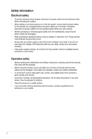
service technician or your retailer. Operation safety • Before installing the motherboard and adding components, carefully read all the manuals away from connectors, slots, sockets and circuitry. • Avoid dust problems with the product, contact a qualified service technician or your retailer. vi - Asus F1A55 R2.0 | F1A55 R2.0 User's Manual - Page 7
you need when installing and configuring the motherboard. How this guide is organized This guide contains the following parts: • Chapter 1: Product introduction This chapter describes the features of the motherboard and the new technology it supports. It includes descriptions of the switches - Asus F1A55 R2.0 | F1A55 R2.0 User's Manual - Page 8
, take note of the following symbols used throughout this manual. DANGER/WARNING: Information to prevent injury to yourself when completing a task. CAUTION: Information to prevent damage to the components when completing a task IMPORTANT: Instructions that you MUST follow to complete a task. NOTE - Asus F1A55 R2.0 | F1A55 R2.0 User's Manual - Page 9
F1A55 R2.0 specifications summary CPU Chipset Memory Graphics Expansion slots Multi-GPU support Storage / RAID LAN Audio USB AMD® Fusion™ A- & E2 series accelerated processors, up to 4 CPU cores, FM1 socket AMD® Turbo Core Technology 2.0 support • The AMD® Turbo Core technology 2.0 support depends - Asus F1A55 R2.0 | F1A55 R2.0 User's Manual - Page 10
F1A55 R2.0 specifications summary ASUS unique features ASUS Exclusive overclocking features Back Panel I/O ports ASUS Exclusive Features - ASUS TurboV - ASUS Low EMI - ASUS AI Charger+ - ASUS MemOK! - ASUS AI Suite II - ASUS Anti-Surge Protection - ASUS UEFI BIOS EZ Mode - Hybrid DIGI+VRM - ASUS - Asus F1A55 R2.0 | F1A55 R2.0 User's Manual - Page 11
F1A55 R2.0 specifications summary Internal I/O connectors / buttons / switches Accessories BIOS features Support DVD Form factor 3 x USB 2.0/1.1 connectors support User Manual 1 x Support DVD 64Mb Flash ROM, UEFI BIOS, PnP, DMI 2.0, WfM 2.0, ACPI 2.0a, SM BIOS 2.6 Drivers ASUS utilities ASUS Update - Asus F1A55 R2.0 | F1A55 R2.0 User's Manual - Page 12
SOCKET FM1 DDR3 DIMM_A1 (64bit, 240-pin module) DDR3 DIMM_A2 (64bit, 240-pin module) DDR3 DIMM_B1 (64bit, 240-pin module) DDR3 DIMM_B2 (64bit, 240-pin module) MemOK! DRAM_LED EATXPWR ASUS F1A55 R2.0 motherboard User Manual 2 x Serial ATA 3.0 Gb/s cables 1 x I/O-Shield User Guide Support - Asus F1A55 R2.0 | F1A55 R2.0 User's Manual - Page 13
) is designed to support up to 5GT/s interface speed and PCI Express™ 2.0 x 16 (at x4 speed) graphics. ATI® CrossFireX™ Technology ATI's CrossFireX™ boosts motherboard uses all high-quality conductive polymer capacitors for durability, improved lifespan, and enhanced thermal capacity. ASUS F1A55 R2 - Asus F1A55 R2.0 | F1A55 R2.0 User's Manual - Page 14
system tuning. Boosted by world-renowned ASUS quality, it creates an allaround platform for a diverse range of applications, including gaming, multimedia, and productivity, all with improved multitasking. * Hybrid DIGI+ VRM functions also available in FM1 socket compatible CPUs MemOK! MemOK! guickly - Asus F1A55 R2.0 | F1A55 R2.0 User's Manual - Page 15
your system by turning your favorite photos into 256-color boot logos. ASUS CrashFree BIOS 3 ASUS CrashFree BIOS 3 is an auto-recovery tool that allows you to restore a corrupted BIOS file using the bundled support DVD or a USB flash disk that contains the BIOS file. ASUS F1A55 R2.0 1-3 - Asus F1A55 R2.0 | F1A55 R2.0 User's Manual - Page 16
restores the CPU parameters to their default settings. ErP ready This motherboard is European Union´s Energy-related Products (ErP) ready, and ErP with regard to energy consumption. This is in line with ASUS' vision of creating environment-friendly and energy-efficient products through product - Asus F1A55 R2.0 | F1A55 R2.0 User's Manual - Page 17
do so can cause you physical injury and damage motherboard components. 1.3.1 Placement direction When installing the motherboard, place it into the chassis in the correct orientation. The edge with external ports goes to the rear part of the chassis as indicated in the image. ASUS F1A55 R2.0 1-5 - Asus F1A55 R2.0 | F1A55 R2.0 User's Manual - Page 18
1.3.2 Screw holes Place six screws into the holes indicated by circles to secure the motherboard to the chassis. Do not overtighten the screws! Doing so can damage the motherboard. Place this side towards the rear of the chassis F1A55 R2.0 1-6 Chapter 1: Product introduction - Asus F1A55 R2.0 | F1A55 R2.0 User's Manual - Page 19
(64bit, 240-pin module) DDR3 DIMM_B2 (64bit, 240-pin module) SOCKET FM1 USB3_E12 LAN1_USB12 AUDIO Realtek® 8111E CHA_FAN1 PWR_FAN PCIEX1_1 Lithium Cell CMOS Power PCIEX1_2 PCIEX16_1 F1A55 R2.0 MemOK! DRAM_LED EATXPWR SATA3G_3 SATA3G_5 SATA3G_4 SATA3G_6 ICS483A SATA3G_1 SATA3G_2 Super - Asus F1A55 R2.0 | F1A55 R2.0 User's Manual - Page 20
and chassis fan connectors (3-pin PWR_FAN, 4-pin CPU_FAN, and 4-pin CHA_FAN1/2) 2. ATX power connectors (24-pin EATXPWR, 4-pin ATX12V) 3. AMD FM1 socket 4. DDR3 DIMM slots 5. MemOK! switch 6. SATA 3.0Gb/s connectors (7-pin SATA3G_1~6) 7. Standby power LED (SB_PWR) 8. System panel connector (20-8 pin - Asus F1A55 R2.0 | F1A55 R2.0 User's Manual - Page 21
/removal, or misplacement/loss/incorrect removal of the PnP cap. To install an APU: 1. Locate the FM1 socket on the motherboard. F1A55 R2.0 F1A55 R2.0 CPU socket FM1 2. Press the lever sideways to unlock the socket, then lift it up to a 90°-100° angle. Socket lever ASUS F1A55 R2.0 1-9 - Asus F1A55 R2.0 | F1A55 R2.0 User's Manual - Page 22
. You can also refer to section 1.6.2 Installing heatsink and fan for instructions. Gold triangle 7. Connect the CPU fan cable to the CPU_FAN connector on the motherboard. CPU_FAN CPU FAN PWM CPU FAN IN CPU FAN PWR GND F1A55 R2.0 F1A55 R2.0 CPU fan connector DO NOT forget to connect the CPU fan - Asus F1A55 R2.0 | F1A55 R2.0 User's Manual - Page 23
module base when installing the CPU or installing other motherboard components. • If you purchased a separate CPU heatsink instructions for the CPU, heatsink, and the retention mechanism. If the instructions in this section do not match the CPU documentation, follow the latter. ASUS F1A55 R2 - Asus F1A55 R2.0 | F1A55 R2.0 User's Manual - Page 24
and fan to the module base. 5. When the fan and heatsink assembly is in place, connect the CPU fan cable to the connector on the motherboard labeled CPU_FAN. DO NOT forget to connect the CPU fan connector! Hardware monitoring errors can occur if you fail to plug this connector. 1-12 Chapter - Asus F1A55 R2.0 | F1A55 R2.0 User's Manual - Page 25
sockets: DIMM_A1 DIMM_A2 DIMM_B1 DIMM_B2 Channel Channel A Channel B Sockets DIMM_A1 and DIMM_A2 DIMM_B1 and DIMM_B2 F1A55 R2.0 F1A55 R2.0 240-pin DDR3 DIMM sockets When overclocking, some AMD CPU models may not support DDR3 1866 MHz or higher frequency DIMMs. motherboard. ASUS F1A55 R2.0 1-13 - Asus F1A55 R2.0 | F1A55 R2.0 User's Manual - Page 26
supported with 16GB or above DIMMs. ASUS manual memory frequency adjustment. • For system stability, use a more efficient memory cooling system to support a full memory load (4 DIMMs) or overclocking condition. F1A55 R2.0 Motherboard - - - 1.5V-1.7V DIMM socket support (Optional) 1 DIMM 2 DIMMs 4 - Asus F1A55 R2.0 | F1A55 R2.0 User's Manual - Page 27
DS - OCZ OCZ3G1866LV4GK 4GB(2 x 2GB) DS - Chip NO. Timing DIMM socket support Voltage (Optional) 1 DIMM 2 DIMMs 4 DIMMs - 9-9-9-24 1.65V • - - 8-8-8-24 1.7V • • • - - - 1.65V • • • - - 8-8-8-24 1.65V • • - - 9 - • • • (continued on the next page) ASUS F1A55 R2.0 1-15 - Asus F1A55 R2.0 | F1A55 R2.0 User's Manual - Page 28
Micron 0YD77D9LGK Transcend TK243PDF3 Micron 9GF27D9KPT 9 1.5V - - - - 9 - - - 9 - - - 9-9-9-20 1.7V 7-7-7-20 1.65V 7-7-7-20 1.65V - - - - - - - - - - - - 9 - 9 - - - 9-9-9-24 1.5V - - - - - - DIMM socket support (Optional) 1 DIMM 2 DIMMs 4 DIMMs - Asus F1A55 R2.0 | F1A55 R2.0 User's Manual - Page 29
slots or the black slots as one pair of dual-channel memory configuration. • C*: Supports two pairs of modules inserted into both the blue slots and the black slots as two pairs of dual-channel memory configuration. Visit the ASUS website at www.asus.com for the latest QVL. ASUS F1A55 R2.0 1-17 - Asus F1A55 R2.0 | F1A55 R2.0 User's Manual - Page 30
adding or removing DIMMs or other system components. Failure to do so can cause severe damage to both the motherboard and the components. 1. Press the retaining clips outward to unlock a DIMM socket. 2. Align a DIMM on the socket such that the notch on the DIMM matches the DIMM slot key on the - Asus F1A55 R2.0 | F1A55 R2.0 User's Manual - Page 31
PCI slots support cards such as a LAN card, SCSI card, USB card, and other cards that comply with PCI specifications. 1.6.4 PCI Express x1 slots This motherboard supports PCI Express x1 network cards, SCSI cards, and other cards that comply with the PCI Express specifications. ASUS F1A55 R2.0 1-19 - Asus F1A55 R2.0 | F1A55 R2.0 User's Manual - Page 32
1.6.5 PCI Express x16 slots This motherboard supports two PCI Express x16 graphics cards that CrossFireX™ mode. See page 1-21 for details. • Connect a chassis fan to the motherboard connector labeled CHA_FAN1/2 when using multiple graphics cards for better thermal environment. IRQ Assignments A - Asus F1A55 R2.0 | F1A55 R2.0 User's Manual - Page 33
the RAM data in CMOS, which include system setup information such as system passwords. F1A55 R2.0 CLRTC 12 23 Normal (Default) F1A55 R2.0 Clear RTC RAM Clear RTC To erase the RTC RAM: 1. Turn OFF the Del> key during the boot process and enter BIOS setup to reenter data. ASUS F1A55 R2.0 1-21 - Asus F1A55 R2.0 | F1A55 R2.0 User's Manual - Page 34
12 11 10 9 87 1. PS/2 Mouse port (green). This port is for a PS/2 mouse. 2. LAN (RJ-45) port. This port allows Gigabit connection to a Local Area Network (LAN) through a network hub. LAN port LED indications Activity/Link LED Status Description OFF No link ORANGE Linked BLINKING Data - Asus F1A55 R2.0 | F1A55 R2.0 User's Manual - Page 35
can only be used under a Windows® OS environment and after USB 3.0 driver installation. • USB 3.0 devices can only be used for data storage. • We strongly recommend that you connect USB 3.0 devices to USB 3.0 ports for faster and better performance for your USB 3.0 devices. ASUS F1A55 R2.0 1-23 - Asus F1A55 R2.0 | F1A55 R2.0 User's Manual - Page 36
FAN PWR GND F1A55 R2.0 Fan connectors DO NOT forget to connect the fan cables to the fan connectors. Insufficient air flow inside the system may damage the motherboard components. These are not jumpers! DO NOT place jumper caps on the fan connectors. • The CPU_FAN connector supports a CPU fan of - Asus F1A55 R2.0 | F1A55 R2.0 User's Manual - Page 37
12 Volts +5V Standby Power OK GND +5 Volts GND +5 Volts GND +3 Volts +3 Volts PIN 1 F1A55 R2.0 ATX power connectors GND +5 Volts +5 Volts +5 Volts -5 Volts GND GND GND PSON# GND -12 http://support.asus. com/PowerSupplyCalculator/PSCalculator.aspx?SLanguage=en-us for details. ASUS F1A55 R2.0 1-25 - Asus F1A55 R2.0 | F1A55 R2.0 User's Manual - Page 38
RSATA_RXN4 RSATA_RXP4 GND RSATA_TXN4 RSATA_TXP4 GND F1A55 R2.0 SATA3G_1 SATA3G_2 GND RSATA_RXN1 RSATA_RXP1 GND [RAID]. See section 2.5.2 SATA Configuration for details. • You must install Windows® XP Service Pack 3 or later versions before using Serial ATA hard disk drives. The Serial ATA RAID - Asus F1A55 R2.0 | F1A55 R2.0 User's Manual - Page 39
the module to a slot opening at the back of the system chassis. COM1 PIN 1 F1A55 R2.0 F1A55 R2.0 Serial port (COM1) connector The COM module is purchased separately. 5. Digital audio connector (4-1 the setting. The S/PDIF module is purchased separately. +5V SPDIFOUT GND ASUS F1A55 R2.0 1-27 - Asus F1A55 R2.0 | F1A55 R2.0 User's Manual - Page 40
(20-8 pin PANEL) This connector supports several chassis-mounted functions. PLED SPEAKER PLED+ PLED+5V Ground Ground Speaker F1A55 R2.0 PANEL PIN 1 IDE_LED+ IDE_LED- PWR Ground Reset Ground IDE_LED PWRSW RESET * Requires an ATX power supply F1A55 R2.0 System panel connector • System power - Asus F1A55 R2.0 | F1A55 R2.0 User's Manual - Page 41
F1A55 R2.0 PIN 1 PIN 1 PIN 1 USB+5V USB_P7USB_P7+ GND USB+5V USB_P9USB_P9+ GND USB+5V USB_P11USB_P11+ GND F1A55 R2.0 USB2.0 connectors Never connect a 1394 cable to the USB connectors. Doing so will damage the motherboard! The USB 2.0 module is purchased separately. ASUS F1A55 R2.0 1-29 - Asus F1A55 R2.0 | F1A55 R2.0 User's Manual - Page 42
with the motherboard may cause system boot failure, and cause the DRAM_LED near the MemOK! to switch lights continuously. Press and hold the MemOK! switch until the DRAM_LED starts blinking to begin automatic memory compatibility tuning for successful boot. F1A55 R2.0 F1A55 R2.0 MemOK! switch - Asus F1A55 R2.0 | F1A55 R2.0 User's Manual - Page 43
in sequence during the motherboard boot process. If an error is found, the LED next to the error device will light up until the problem is solved. This user-friendly design provides an intuitive way to locate the root problem quickly. F1A55 R2.0 DRAM LED F1A55 R2.0 DRAM LED ASUS F1A55 R2.0 1-31 - Asus F1A55 R2.0 | F1A55 R2.0 User's Manual - Page 44
screen which contains the unique features of ASUS motherboard. Click Drivers, Utilities, Make Disk, Manual, and Contact tabs to display their respective menus. The following screen is for reference only. Click an icon to display Support DVD/motherboard information Click an item to install If - Asus F1A55 R2.0 | F1A55 R2.0 User's Manual - Page 45
is available in the support DVD that comes with the motherboard package. Installing ASUS Update To install ASUS Update: 1. Place the support DVD in the optical drive. The Drivers menu appears. 2. Click the Utilities tab, then click AI Suite II. 3. Follow the onscreen instructions to complete the - Asus F1A55 R2.0 | F1A55 R2.0 User's Manual - Page 46
version that you wish to download then click Next. The ASUS Update utility is capable of Follow the onscreen instructions to complete the updating process. 2.1.2 ASUS EZ Flash 2 The ASUS EZ Flash 2 when the update process is done. • This function supports USB flash disks formatted using FAT32/16 on a - Asus F1A55 R2.0 | F1A55 R2.0 User's Manual - Page 47
BIOS file using the motherboard support DVD or a USB flash drive that contains the updated BIOS file. • Before using this utility, rename the BIOS file in the removable device into F1A55-R2-ASUS-0309.CAP. • The BIOS file in the support DVD may not be the latest version. Download the latest BIOS file - Asus F1A55 R2.0 | F1A55 R2.0 User's Manual - Page 48
may not be same as shown. Before updating BIOS 1. Prepare the motherboard support DVD and a USB flash drive formatted using FAT32/16 on a single partition. 2. Download the latest BIOS file and BIOS Updater from the ASUS website at http://support.asus.com and save them on the USB flash drive. NTFS is - Asus F1A55 R2.0 | F1A55 R2.0 User's Manual - Page 49
update the BIOS file using BIOS Updater: 1. At the FreeDOS prompt, type bupdater /pc /g and press . 2. The BIOS Updater screen appears as below. F1A55 R2.0 0309 F1A55-R2-ASUS-0309.CAP 8194 2012-05-16 15:25:48 3. Press to switch between screen fields and use the keys - Asus F1A55 R2.0 | F1A55 R2.0 User's Manual - Page 50
. The BIOS screens include navigation keys and brief online help to guide you in using the BIOS Setup program. Entering BIOS Setup at Visit the ASUS website at www.asus.com to download the latest BIOS file for this motherboard. • Ensure that a USB mouse is connected to your motherboard if you - Asus F1A55 R2.0 | F1A55 R2.0 User's Manual - Page 51
changed. Refer to the Setup Mode item in section 2.7 Boot menu for details. Displays the CPU/motherboard temperature, CPU voltage output, and CPU/chassis fan speed Selects the display language of the BIOS is available only when the boot device is installed to the system. ASUS F1A55 R2.0 2-7 - Asus F1A55 R2.0 | F1A55 R2.0 User's Manual - Page 52
an example of the Advanced Mode. Refer to the following sections for the detailed configurations. To access the EZ Mode, click Exit, then select ASUS EZ Mode. Back button Menu items Menu bar Configuration fields General help Submenu item Pop-up window Navigation keys Menu bar The menu bar on - Asus F1A55 R2.0 | F1A55 R2.0 User's Manual - Page 53
not user-configurable. A configurable field is highlighted when selected. To change the value of a field, select it and press to display a list of options. ASUS F1A55 R2.0 2-9 - Asus F1A55 R2.0 | F1A55 R2.0 User's Manual - Page 54
2.3 Main menu The Main menu screen appears when you enter the Advanced Mode of the BIOS Setup program. The Main menu provides you an overview of the basic system information, and allows you to set the system date, time, language, and security settings. 2.3.1 System Language [English] Allows you to - Asus F1A55 R2.0 | F1A55 R2.0 User's Manual - Page 55
when prompted to create/confirm the password. After you clear the password, the User Password item on top of the screen shows Not Installed. ASUS F1A55 R2.0 2-11 - Asus F1A55 R2.0 | F1A55 R2.0 User's Manual - Page 56
values can cause the system to malfunction. The configuration options for this section vary depending on the CPU and DIMM model you installed on the motherboard. Scroll down to display the following items: 2-12 Chapter 2: Getting started - Asus F1A55 R2.0 | F1A55 R2.0 User's Manual - Page 57
. APU Frequency [XXX] This item appears only when you set the AI Overclock Tuner item to [Manual]. Use the and keys to adjust the value. You can also key in the desired value disable the EPU power saving function. Configuration options: [Disabled] [Enabled] ASUS F1A55 R2.0 2-13 - Asus F1A55 R2.0 | F1A55 R2.0 User's Manual - Page 58
] Allows you to control the power phase based on the CPU's demands. Configuration options: [Standard] [Optimized] [Extreme] [Manual Adjustment] DO NOT remove the thermal module when switching to Extreme and Manual Mode. The thermal conditions should be monitored. 2-14 Chapter 2: Getting started - Asus F1A55 R2.0 | F1A55 R2.0 User's Manual - Page 59
APU 1.2V Voltage [Auto] Allows you to set the APU (Accelerated Processor Unit) 1.2V voltage. The values range from 1.2000V to 1.8000V with a 0.01V interval. ASUS F1A55 R2.0 2-15 - Asus F1A55 R2.0 | F1A55 R2.0 User's Manual - Page 60
2.4.15 VDDA Voltage [Auto] Allows you to set the VDDA voltage. The values range from 2.5000V to 2.8000V with a 0.01V interval. • The values of the CPU Offset Voltage, VDDNB Offset Voltage, DRAM Voltage, SB 1.1V Voltage, 1.1Vsb Voltage, APU1.2V Voltage, and VDDA Voltage items are labeled in different - Asus F1A55 R2.0 | F1A55 R2.0 User's Manual - Page 61
. Limit CPUID Maximum [Disabled] [Enabled] Allows legacy operating systems to boot even without support for CPUs with extended CPUID functions. [Disabled] Disables this function. C6 Mode [Auto] onboard channel SATA port. Configuration options: [Disable link] [Enabled] ASUS F1A55 R2.0 2-17 - Asus F1A55 R2.0 | F1A55 R2.0 User's Manual - Page 62
The AHCI allows the onboard storage driver to enable advanced Serial ATA features that S.M.A.R.T. (Self-Monitoring, Analysis and Reporting Technology) is a monitor system. When read/write item shows None. Legacy USB Support [Enabled] [Enabled] Enables the support for USB devices on legacy - Asus F1A55 R2.0 | F1A55 R2.0 User's Manual - Page 63
Disabled] Allows you to enable or disable the iGPU Multi-Monitor. For Lucid Virtu Universal MVP function support, set this item to [Enabled] to empower both the integrated and discrete graphic cards. The ] for SPDIF audio output. [HDMI] Sets to [HDMI] for HDMI audio output. ASUS F1A55 R2.0 2-19 - Asus F1A55 R2.0 | F1A55 R2.0 User's Manual - Page 64
allows you to enable or disable the PXE OptionRom of the Realtek LAN controller. Configuration options: [Enabled] [Disabled] Asmedia USB 3.0 Controller . [Disabled] Disables the controller. Asmedia USB 3.0 Battery Charging Support [Disabled] This item appears only when the Asmedia USB 3.0 - Asus F1A55 R2.0 | F1A55 R2.0 User's Manual - Page 65
LAN or Support [Enabled] This item allows user to disable or enable the Ipv4 PXE Boot support. Configuration options: [Disable Link] [Enable] Ipv6 PXE Support [Enabled] This item allows user to disable or enable the Ipv6 PXE Boot support. Configuration options: [Disable Link] [Enable] ASUS F1A55 R2 - Asus F1A55 R2.0 | F1A55 R2.0 User's Manual - Page 66
to change the fan settings. Scroll down to display the following items: 2.6.1 CPU Temperature / MB Temperature [xxxºC/xxxºF] The onboard hardware monitor automatically detects and displays the CPU and motherboard temperatures. Select Ignore if you do not wish to display the detected temperatures - Asus F1A55 R2.0 | F1A55 R2.0 User's Manual - Page 67
fan operation. [Turbo] Sets to [Turbo] to achieve maximum CPU fan speed. [Manual] Sets to [Manual] to assign detailed fan speed control parameters. The following four items appear only when you Q-Fan control feature. [Enabled] Enables the Chassis Q-Fan control feature. ASUS F1A55 R2.0 2-23 - Asus F1A55 R2.0 | F1A55 R2.0 User's Manual - Page 68
Turbo] Sets to [Turbo] to achieve maximum chassis fan speed. [Manual] Sets to [Manual] to assign detailed fan speed control parameters. The following four items appear if you do not want to detect this item. 2.6.6 Anti Surge Support [Enabled] This item allows you to enable or disable the Anti - Asus F1A55 R2.0 | F1A55 R2.0 User's Manual - Page 69
display feature. Disables the full screen logo display feature. Set this item to [Enabled] to use the ASUS MyLogo 2™ feature. Post Report [5 sec] This item appears only when the Full Screen Logo item [4 sec] [5 sec] [6 sec] [7 sec] [8 sec] [9 sec] [10 sec] [Until Press ESC] ASUS F1A55 R2.0 2-25 - Asus F1A55 R2.0 | F1A55 R2.0 User's Manual - Page 70
Logo appears. • To access Windows OS in Safe Mode, do any of the following: • Press when ASUS Logo appears. • Press after POST. 2.7.9 Boot Override These items displays the available devices. The number of device items that appears on the screen depends - Asus F1A55 R2.0 | F1A55 R2.0 User's Manual - Page 71
BIOS file only coming from the same memory/ CPU configuration and BIOS version. 2.8.3 ASUS SPD Information DIMM Slot # [DIMM_A1] Displays the Serial Presence Detect (SPD) information of the DIMM module installed on the selected slot. Configuration options: [DIMM_A1] [DIMM_A2] ASUS F1A55 R2.0 2-27 - Asus F1A55 R2.0 | F1A55 R2.0 User's Manual - Page 72
program without saving your changes. When you select this option or if you press , a confirmation window appears. Select Yes to discard changes and exit. ASUS EZ Mode This option allows you to enter the EZ Mode screen. Launch EFI Shell from filesystem device This option allows you to attempt to - Asus F1A55 R2.0 | F1A55 R2.0 User's Manual - Page 73
manufacturer's instructions, may Le fonctionnement est soumis aux deux conditions suivantes : (1) cet appareil ne doit pas provoquer d'interférences et (2) cet appareil doit accepter toute interférence, y compris celles susceptibles de provoquer un fonctionnement non souhaité de l'appareil. F1A55 R2 - Asus F1A55 R2.0 | F1A55 R2.0 User's Manual - Page 74
substances in our products at ASUS REACH website at http://csr.asus.com/english/REACH.htm. DO NOT throw the motherboard in municipal waste. This the battery should not be placed in municipal waste. ASUS Recycling/Takeback Services ASUS recycling and takeback programs come from our commitment to - Asus F1A55 R2.0 | F1A55 R2.0 User's Manual - Page 75
Fax +49-2102-959911 Web site www.asus.de Online contact www.asus.de/sales Technical Support Telephone Support Fax Online support +49-1805-010923* +49-2102-9599-11 support.asus.com * EUR 0.14/minute from a German fixed landline; EUR 0.42/minute from a mobile phone. F1A55 R2.0 A-3 - Asus F1A55 R2.0 | F1A55 R2.0 User's Manual - Page 76
, TAIWAN R.O.C. Country: TAIWAN Authorized representative in Europe: ASUS COMPUTER GmbH Address, City: HARKORT STR. 21-23, 40880 RATINGEN Country: GERMANY declare the following apparatus: Product name : Motherboard Model name : F1A55 R2.0 conform with the essential requirements of the
-
 1
1 -
 2
2 -
 3
3 -
 4
4 -
 5
5 -
 6
6 -
 7
7 -
8
-
9
-
10
-
11
-
12
-
13
-
14
-
15
-
16
-
17
-
18
-
19
-
20
-
21
-
22
-
23
-
24
-
25
-
26
-
27
-
28
-
29
-
30
-
31
-
32
-
33
-
34
-
35
-
36
-
37
-
38
-
39
-
40
-
41
-
42
-
43
-
44
-
45
-
46
-
47
-
48
-
49
-
50
-
51
-
52
-
53
-
54
-
55
-
56
-
57
-
58
-
59
-
60
-
61
-
62
-
63
-
64
-
65
-
66
-
67
-
68
-
69
-
70
-
71
-
72
-
73
-
74
-
75
-
76
 |
 |

Motherboard
F1A55 R2.0