Asus F1A55 R2.0 F1A55 R2.0 User's Manual - Page 22
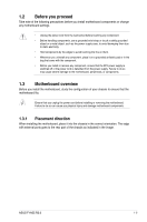
F1A55 R2.0 CPU fan connector
 |
View all Asus F1A55 R2.0 manuals
Add to My Manuals
Save this manual to your list of manuals |
Page 22 highlights
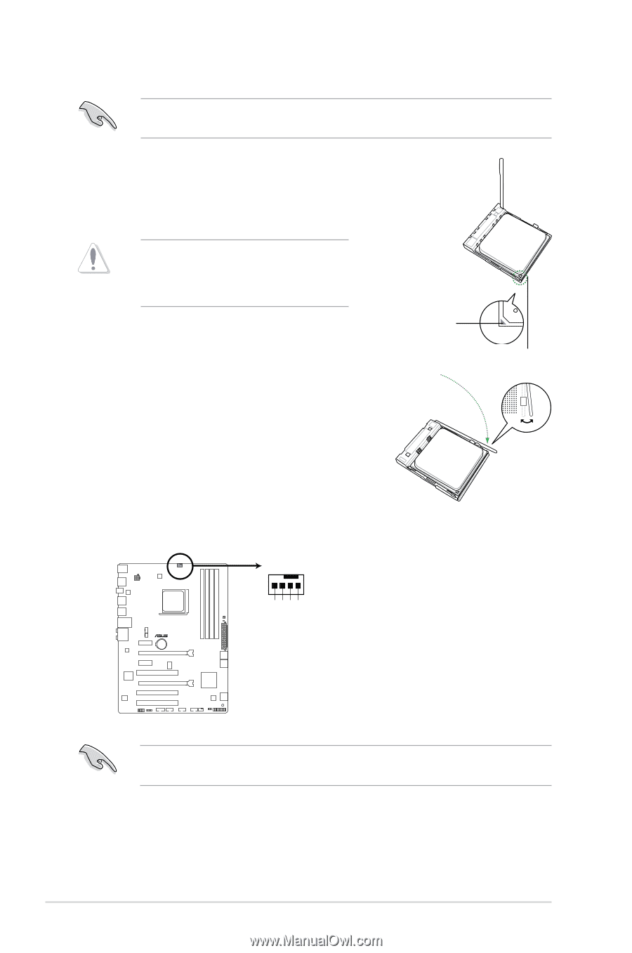
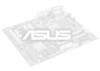
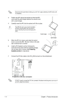
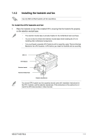
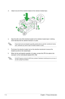
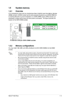
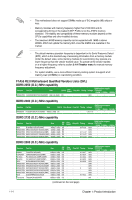
Ensure that the socket lever is lifted up to a 90°-100° angle; otherwise, the APU will not fit in completely. 3. Position the APU above the socket such that the APU corner with the gold triangle matches the socket corner with a small triangle. 4. Carefully insert the APU into the socket until it fits in place. The APU fits only in one correct orientation. DO NOT force the APU into the socket to prevent bending the pins and damaging the APU! Small triangle 5. When the APU is in place, push down the socket lever to secure the APU. The lever clicks on the side tab to indicate that it is locked. 6. Install a APU heatsink and fan following the instructions that comes with the heatsink package. You can also refer to section 1.6.2 Installing heatsink and fan for instructions. Gold triangle 7. Connect the CPU fan cable to the CPU_FAN connector on the motherboard. CPU_FAN CPU FAN PWM CPU FAN IN CPU FAN PWR GND F1A55 R2.0 F1A55 R2.0 CPU fan connector DO NOT forget to connect the CPU fan connector! Hardware monitoring errors can occur if you fail to plug this connector. 1-10 Chapter 1: Product introduction
-
 1
1 -
2
-
3
-
4
-
5
-
6
-
7
-
8
-
9
-
10
-
11
-
12
-
13
-
14
-
15
-
16
-
 17
17 -
 18
18 -
 19
19 -
 20
20 -
 21
21 -
 22
22 -
 23
23 -
 24
24 -
 25
25 -
 26
26 -
 27
27 -
28
-
29
-
30
-
31
-
32
-
33
-
34
-
35
-
36
-
37
-
38
-
39
-
40
-
41
-
42
-
43
-
44
-
45
-
46
-
47
-
48
-
49
-
50
-
51
-
52
-
53
-
54
-
55
-
56
-
57
-
58
-
59
-
60
-
61
-
62
-
63
-
64
-
65
-
66
-
67
-
68
-
69
-
70
-
71
-
72
-
73
-
74
-
75
-
76
 |
 |