Asus P I-P55T2P4 User Manual
Asus P I-P55T2P4 Manual
 |
View all Asus P I-P55T2P4 manuals
Add to My Manuals
Save this manual to your list of manuals |
Asus P I-P55T2P4 manual content summary:
- Asus P I-P55T2P4 | User Manual - Page 1
R P/I-P55T2P4 Pentium Motherboard USER'S MANUAL - Asus P I-P55T2P4 | User Manual - Page 2
. For previous or updated manuals, BIOS, drivers, or product release information you may visit the ASUS home page at http://www.asus.com.tw/ or contact ASUS from the following page. © Copyright 1997 ASUSTeK COMPUTER INC. All rights reserved. Product Name: ASUS P/I-P55T2P4 Manual Revision: 3.11 - Asus P I-P55T2P4 | User Manual - Page 3
: [email protected] ASUS COMPUTER GmbH Marketing Info: Address: Harkort Str. 25, 40880 Ratingen, BRD, Germany Telephone: 49-2102-445011 Fax: 49-2102-442066 Email: [email protected] Technical Support: BBS: 49-2102-448690 Email: [email protected] ASUS P/I-P55T2P4 User's Manual III - Asus P I-P55T2P4 | User Manual - Page 4
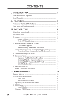
Connectors 19 Power Connection Procedures 25 IV. BIOS SOFTWARE 26 Support Software 26 Flash Memory Writer Utility 26 Main Menu 26 Advanced Features Menu 27 Updating your Motherboard's BIOS 28 6. BIOS Setup 29 Load Defaults 30 Standard CMOS Setup 30 IV ASUS P/I-P55T2P4 User's Manual - Asus P I-P55T2P4 | User Manual - Page 5
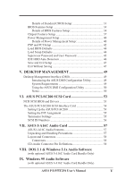
DMI Configuration Utility 49 System Requirements 49 Using the ASUS DMI Configuration Utility 50 Notes 50 VI. ASUS PCI-SC200 SCSI Card 53 NCR SCSI BIOS and Drivers 53 The ASUS PCI-SC200 SCSI Interface Card 54 Setting Up the ASUS PCI-SC200 54 Setting the INT Assignment 55 Terminator Settings - Asus P I-P55T2P4 | User Manual - Page 6
radio frequency energy and, if not installed and used in accordance with manufacturer's instructions, may cause harmful interference to radio communications. However, there is no guarantee Interference Regulations of the Canadian Department of Communications. VI ASUS P/I-P55T2P4 User's Manual - Asus P I-P55T2P4 | User Manual - Page 7
your retailer. The ASUS P/I-P55T2P4 motherboard 2 serial port ribbon cables attached to a mounting bracket 1 parallel ribbon cable with mounting bracket 1 IDE ribbon cable 1 floppy ribbon cable Support drivers and utilities as follows: • Flash Memory Writer utility to update the FLASH BIOS • Desktop - Asus P I-P55T2P4 | User Manual - Page 8
ASUS Motherboard The ASUS P/I-P55T2P4 is carefully designed for the demanding PC user who wants a great many features in a small package. This motherboard: • Easy Installation: Is equipped with BIOS that supports PCI card or the ASUS MediaBus Card. • ASUS MediaBus Rev 2.0: Features an expansion - Asus P I-P55T2P4 | User Manual - Page 9
infrared port module for wireless interface and a PS/2 mouse cable set. • NCR SCSI BIOS: This motherboard has firmware that supports the optional ASUS PCI-SC200 SCSI controller cards. Parts of the ASUS Motherboard 3 ISA Slots Programmable Flash ROM 3 PCI Slots Parallel & Serial Ports Super Multi - Asus P I-P55T2P4 | User Manual - Page 10
III. INSTALLATION Map of the ASUS Motherboard ISA Slot 2 ISA Slot 3 JP2 Boot Block Write (Dis/En) IDE Floppy Drives P8 MediaBus 2.0 Pipelined Burst Level 2 Cache Expansion Slot TAG SRAM Upgrade JP7 CMOS Operation/Clear JP4 Cacheable 64/512MB JP8 JP9 JP10 BUS Freq CPU ZIF Socket 7 JP5 - Asus P I-P55T2P4 | User Manual - Page 11
Block) Serial Port COM1 & COM2 (10-pin Blocks) Floppy Drive Connector (34-pin Block) Motherboard Power Connector (12-pin Block) Primary/Secondary IDE Connectors (40-pin Blocks) IDE LED Activity (4-pins) CPU 12V Cooling Fan Connector Infrared Port Module Connector ASUS P/I-P55T2P4 User's Manual 5 - Asus P I-P55T2P4 | User Manual - Page 12
6. Setup the BIOS Software 1. Jumpers Several hardware settings are made through the use of jumper caps to connect jumper pins (JP) on the motherboard. See "Map of the Motherboard" on page 4 the component whenever the components are separated from the system. 6 ASUS P/I-P55T2P4 User's Manual - Asus P I-P55T2P4 | User Manual - Page 13
This sets the operation mode of the boot block area of the BIOS Flash ROM to allow programming in the Enabled position. Programming Disabled Enabled JP2 [1-2] (Default) [2-3] JP2 123 Disabled (Default) JP2 123 Enabled Boot Block Programming (Disable / Enable) ASUS P/I-P55T2P4 User's Manual 7 - Asus P I-P55T2P4 | User Manual - Page 14
Motherboard" for locations) and a stored in the CMOS RAM of the Real BIOS setup to re-enter user preferences. Selections JP7 Operation [open] (Default) Clear Data [short] (momentarily) JP7 JP7 Operation (Default) Clear Data RTC RAM (Operation / Clear Data) 8 ASUS P/I-P55T2P4 User's Manual - Asus P I-P55T2P4 | User Manual - Page 15
2.8 Volts 2.7 Volts 2.5 Volts JP20 [9-10] [7-8] [5-6] (Default) [3-4] [1-2] [9-10] JP20 K6-PR233 (3.2 Volts) [7-8] JP20 K6-PR166,200 (2.9 Volts) [5-6] JP20 P55C/6x86MX (2.8V) (Default) CPU Vcore Voltage Selection ASUS P/I-P55T2P4 User's Manual 9 - Asus P I-P55T2P4 | User Manual - Page 16
-K6-PR233 AMD-K6-PR200 AMD-K6-PR166 AMD-K5-PR133/100 AMD-K5-PR120/90 AMD-K5-PR75 Freq. 233MHz 200MHz 166MHz Rev 2.7 or later is supported on this motherboard (see next page). Bootup screen will show 6x86-P166+ with the Cyrix PR166+ installed on this motherboard. 10 ASUS P/I-P55T2P4 User's Manual - Asus P I-P55T2P4 | User Manual - Page 17
CPU Identification The only Cyrix CPU that is supported on this motherboard is labeled Cyrix 6x86-PR166+ but must be or use a cache module with an extended TAG SRAM (such as 256KB ASUS CM1 Rev 3.0 with 2 TAG SRAM's) but not both and set this jumper to (64MB/512MB) ASUS P/I-P55T2P4 User's Manual 11 - Asus P I-P55T2P4 | User Manual - Page 18
motherboard supports four 72-pin SIMMs of 4MB, 8MB, 16MB, 32MB, or 64MB to form a memory size between 8MB to 256MB. The DRAM can be either 60ns or 70ns Fast Page Mode (Asymmetric or Symmetric) or EDO. To support setup is required in BIOS Chipset Setup "Auto Configuration ASUS P/I-P55T2P4 User's Manual - Asus P I-P55T2P4 | User Manual - Page 19
) Mounting Hole 4. The plastic guides should go through the two "Mounting Holes" on the sides and the "Metal Clips" should snap on the other side. 5. To release the memory module, squeeze both "Metal Clips" outwards and rock the module out of the "Metal Clips". ASUS P/I-P55T2P4 User's Manual 13 - Asus P I-P55T2P4 | User Manual - Page 20
the orientation as shown. Compatible Cache Modules for this Motherboard SIMM Cache Module ASUS CM1 Rev 1.0 ASUS CM1 Rev 1.3 ASUS CM4 Rev 1.5 ASUS CM1 Rev 1.6 ASUS CM1 Rev 3.0 COAST 1.1 COAST 1.2 COAST 1.3 COAST 2.0 COAST TAG SRAM into the TAG SRAM Upgrade Socket. 14 ASUS P/I-P55T2P4 User's Manual - Asus P I-P55T2P4 | User Manual - Page 21
, the CPU can overheat and cause damage to both the CPU and the motherboard. (See page 24 "CPU Cooling Fan Connector.) To install a CPU, the notched corner of the CPU with the white dot as your guide. The white dot should point towards the end the of the lever Dot ASUS P/I-P55T2P4 User's Manual 15 - Asus P I-P55T2P4 | User Manual - Page 22
do so may cause severe damage to both your motherboard and expansion cards. First read your expansion card the BIOS if necessary (such as "IRQ xx Used By ISA: Yes" in PNPAND PCI SETUP) 9. Install the necessary software drivers for your free for expansion cards. 16 ASUS P/I-P55T2P4 User's Manual - Asus P I-P55T2P4 | User Manual - Page 23
jumpers manually and then of your used and free IRQs. For Windows 95 problems when those two devices are in use at the same time. To simplify this process this motherboard BIOS BIOS design, the BIOS automatically assigns on this motherboard use an this motherboard are handled of the BIOS Setup utility. - Asus P I-P55T2P4 | User Manual - Page 24
problems in order to maximize the Plug and Play advantages. The add-on card inserts into the shared PCI 4 / MediaBus 2.0 Slot. NOTE: This motherboard uses MediaBus Rev. 2.0. The previous MediaBus cards designed for MediaBus Rev the above SCSI features Adaptec, Inc. 18 ASUS P/I-P55T2P4 User's Manual - Asus P I-P55T2P4 | User Manual - Page 25
of the connector. The four corners of the connectors are labeled on the motherboard. Pin 1 is the side closest to the power connector on hard drives in BIOS FEATURES SETUP. 1 234 58 1 234 58 1: GND 2: DATA 3: NC 4: VCC 5: CLK 8: NC PS/2 Mouse Module Connector ASUS P/I-P55T2P4 User's Manual 19 - Asus P I-P55T2P4 | User Manual - Page 26
can enable the parallel port and choose the IRQ through BIOS Setup on page 36 "Onboard Parallel Port." (Pin (Two 10-pin blocks) These connectors support the provided serial port ribbon cables with devices or other serial devices. See page 35 for BIOS configuration of "Onboard Serial Port". (Pin 10 - Asus P I-P55T2P4 | User Manual - Page 27
) This connector supports the provided floppy drive the middle. Using a slight angle, align the plastic guide pins on the lead to their receptacles on the Motherboard P9 -5V -12V +5V RED RED RED WHT BLK BLK BLK BLK BLU YLW RED ORG P8 Power Plugs from Power Supply ASUS P/I-P55T2P4 User's Manual - Asus P I-P55T2P4 | User Manual - Page 28
primary IDE connector and another ribbon cable on the secondary IDE connector. BIOS now supports SCSI device or IDE CD-ROM bootup (see "HDD Sequence SCSI/IDE First" & "Boot Sequence" in activity indicator light on the system cabinet. IDE LED + IDE Activity LED 22 ASUS P/I-P55T2P4 User's Manual - Asus P I-P55T2P4 | User Manual - Page 29
(CON1) The motherboard's turbo function is leaving it shorted will not cause any problems. May require one or two pushes depending on the position , "Suspend Switch" in the POWER MANAGEMENT SETUP of the BIOS software should be on the default setting of Enable. 11. ASUS P/I-P55T2P4 User's Manual 23 - Asus P I-P55T2P4 | User Manual - Page 30
opening on system cases that support this feature. You must also configure the setting through BIOS setup on page 36 " motherboard according to the pin definitions. Front View Back View +5V IRRX IRTX NC GND Infrared Module Connector IRTX +5V GND NC IRRX 24 ASUS P/I-P55T2P4 User's Manual - Asus P I-P55T2P4 | User Manual - Page 31
test. Recheck your jumper settings and connections or call your authorized dealer for assistance. 7. During power-on, hold down the key to enter BIOS setup. Follow the next section "BIOS SOFTWARE" for instructions. III. INSTALLATION (Power Connections) ASUS P/I-P55T2P4 User's Manual 25 - Asus P I-P55T2P4 | User Manual - Page 32
support software. PFLASH.EXE - This is the Flash Memory Writer utility that updates the BIOS by uploading a new BIOS file to the programmable flash ROM chip on the motherboard. To determine the BIOS the BIOS to the floppy diskette. IV. BIOS (Flash Memory Writer) 26 ASUS P/I-P55T2P4 User's Manual - Asus P I-P55T2P4 | User Manual - Page 33
Update BIOS Including Boot Block and ESCD This option updates the Boot Block, the motherboard BIOS and the PnP ESCD Parameter Block from a new BIOS file. NOTE: "Update BIOS Main Block from File" and "Update BIOS "CONFIG.SYS" files. IV. BIOS (Flash Memory Writer) ASUS P/I-P55T2P4 User's Manual 27 - Asus P I-P55T2P4 | User Manual - Page 34
IV. BIOS SOFTWARE Updating your Motherboard's BIOS 1. Download an updated BIOS file from Bulletin Board Services (BBS) or the internet (WWW) and save to the diskette you created in step 1 of the Main Menu. See ASUS CONTACT INFORMATION on page II. 2. Turn off your computer and open the system cabinet - Asus P I-P55T2P4 | User Manual - Page 35
IV. BIOS SOFTWARE 6. BIOS Setup The motherboard supports two programmable Flash ROM chips: 5 Volt and 12 Volt. Either of these memory chips can be updated when BIOS upgrades are released. Use the Flash Memory Writer utility to download the new BIOS file into the ROM chip as described in detail in - Asus P I-P55T2P4 | User Manual - Page 36
BIOS Defaults" option loads the minimized settings for troubleshooting motherboard is already installed in a working system, you will not need to select this option anymore. However, if the configuration stored in the CMOS CMOS battery weakens. IV. BIOS (Standard CMOS) ASUS P/I-P55T2P4 User's Manual - Asus P I-P55T2P4 | User Manual - Page 37
devices. Each channel can support up to two hard motherboard (see section VI for instructions). If you install other vendor's SCSI controller card, please refer to their respective documentations on how to install the required SCSI drivers. IV. BIOS (Standard CMOS) ASUS P/I-P55T2P4 User's Manual - Asus P I-P55T2P4 | User Manual - Page 38
support BIOS, new IDE hard disk drives must be partitioned (such as with FDISK) and then formatted before data can be read from and write on. Primary IDE hard disk drives must have its partition set to active (also possible with FDISK). IV. BIOS (Standard CMOS) 32 ASUS P/I-P55T2P4 User's Manual - Asus P I-P55T2P4 | User Manual - Page 39
field and then select the drive type using the left- or right-arrow key. Floppy 3 Mode Support This is the Japanese standard floppy drive. The standard stores 1.2MB in a 3.5" diskette. This But Keyboard All, But Diskette All, But Disk/Key IV. BIOS (Standard CMOS) ASUS P/I-P55T2P4 User's Manual 33 - Asus P I-P55T2P4 | User Manual - Page 40
entries here are required by the motherboard's design to remain in their default settings. IV. BIOS (BIOS Features) A section at the lower allow the operation to continue or use a bootable virus-free floppy disk to reboot and investigate your system. The default 34 ASUS P/I-P55T2P4 User's Manual - Asus P I-P55T2P4 | User Manual - Page 41
hard disk and then the floppy drive, that is, C, A. Boot Up Floppy Seek When enabled, the BIOS will seek the floppy "A" drive one time. By setup default, this field is set to Disabled. Floppy and therefore the PS/2 Mouse will not function. IV. BIOS (BIOS Features) ASUS P/I-P55T2P4 User's Manual 35 - Asus P I-P55T2P4 | User Manual - Page 42
the time interval, in milliseconds, for displaying the first and second characters. Four delay rate options are available: 250 (default), 500, 750 and 1000. IV. BIOS (BIOS Features) 36 ASUS P/I-P55T2P4 User's Manual - Asus P I-P55T2P4 | User Manual - Page 43
chipset. Control keys for this screen are the same as for the previous screen. (BIOS Features) IV. BIOS (Chipset Features) Auto Configuration The default setting of 60ns DRAM sets the optimal timings for only access memory up to 16MB. The default is Disabled. ASUS P/I-P55T2P4 User's Manual 37 - Asus P I-P55T2P4 | User Manual - Page 44
(Chipset Features) IV. BIOS SOFTWARE [DRAM and ECC] If all your DRAM modules have parity chips (e.g. 8 chips + 4 parity chips), they are considered 36bits. This motherboard sums the memory per 3E8H/IRQ4, 2E8H/IRQ10, and Disabled for the onboard serial connector. 38 ASUS P/I-P55T2P4 User's Manual - Asus P I-P55T2P4 | User Manual - Page 45
the onboard infrared feature and sets the second serial UART to support the infrared module connector on the motherboard. If your system already has a second serial port connected of Auto will allow autodetection to ensure optimal performance. IV. BIOS IV. BIOS ASUS P/I-P55T2P4 User's Manual 39 - Asus P I-P55T2P4 | User Manual - Page 46
to keep the system time updated when the computer enters suspend mode activated by the BIOS Power Management. For DOS environments Power Management System) features allow the BIOS to control the video display card if it supports the DPMS feature. Blank Screen only ASUS P/I-P55T2P4 User's Manual - Asus P I-P55T2P4 | User Manual - Page 47
IV. BIOS SOFTWARE Suspend Switch This field enables or disables the SMI connector on the motherboard. This connector connects to the lead from the Suspend switch mounted on software alarm clock or event calendar can wake up the system. IV. BIOS (Power Management) ASUS P/I-P55T2P4 User's Manual 41 - Asus P I-P55T2P4 | User Manual - Page 48
operating system to configure the PCI bus slots instead of using the BIOS. Default setting is No. Slot 1 (RIGHT) IRQ to Slot setting of "32 PCI Clock" enables maximum PCI performance for this motherboard. IRQ xx Used By ISA These fields indicate whether or not the ASUS P/I-P55T2P4 User's Manual - Asus P I-P55T2P4 | User Manual - Page 49
This motherboard supports Universal Serial Bus (USB) devices but current operating systems do not. The default is set to Disabled until support disks and USB devices are available in which time you can set this function to Enabled. IV. BIOS (Plug & Play / PCI) (Power Management) ASUS P/I-P55T2P4 - Asus P I-P55T2P4 | User Manual - Page 50
troubleshooting default values permanently stored in the BIOS ROM. These default settings are non-optimal and disable all high performance features. To load these default settings, highlight "Load BIOS on the Standard CMOS Setup screen. IV. BIOS (Load Defaults) 44 ASUS P/I-P55T2P4 User's Manual - Asus P I-P55T2P4 | User Manual - Page 51
to the main screen. IV. BIOS (Passwords) To implement the password protection, specify in the "Security Option" field of the BIOS Features Setup screen when the system : If you forget the password, see CMOS RAM in section III for procedures on clearing the CMOS. ASUS P/I-P55T2P4 User's Manual 45 - Asus P I-P55T2P4 | User Manual - Page 52
drive, and automatically enters them into the Standard CMOS Setup screen. IV. BIOS (Hard Drive Detect) Up to four IDE you want to use another controller that supports four drives, you must disable the onboard problem if the drive is new and there is nothing on it. 46 ASUS P/I-P55T2P4 User's Manual - Asus P I-P55T2P4 | User Manual - Page 53
BIOS (Save & Exit) Exit Without Saving Select this option to exit the Setup utility without saving the modifications you specify during the current session. To exit without saving, highlight the "Exit Without Saving" option on the main screen and then press . ASUS P/I-P55T2P4 User's Manual - Asus P I-P55T2P4 | User Manual - Page 54
(This page was intentionally left blank) 48 ASUS P/I-P55T2P4 User's Manual - Asus P I-P55T2P4 | User Manual - Page 55
be manually entered through the DMI Configuration Utility and updated into the MIFD. This DMI Configuration Utility provides the same reliability as PnP updating and will prevent the refreshing failures associated with updating the entire BIOS. System Requirements The motherboard BIOS must support - Asus P I-P55T2P4 | User Manual - Page 56
the ASUS DMI Configuration BIOS Auto Detect *** appears on the right for each menu item on the left side that has been auto detected by the system BIOS. A heading, *** User Modified *** will appear on the right for menu items that has been modified by the user. 50 ASUS P/I-P55T2P4 User's Manual - Asus P I-P55T2P4 | User Manual - Page 57
path and file name here. Load BIOS Defaults V. DMI (Using DMI Utility) You can load the BIOS defaults from a MIFD file and can clear all user modified and added data. You must reboot your computer in order for the defaults to be saved back into the Flash BIOS. ASUS P/I-P55T2P4 User's Manual 51 - Asus P I-P55T2P4 | User Manual - Page 58
(This page was intentionally left blank) 52 ASUS P/I-P55T2P4 User's Manual - Asus P I-P55T2P4 | User Manual - Page 59
SCSI Cards (SCSI BIOS) VI. ASUS PCI SCSI Cards Symbios SCSI BIOS and Drivers Aside from the system BIOS, the Flash memory chip on the motherboard also contains the Symbios SCSI BIOS. This Symbios SCSI BIOS works in conjunction with the optional ASUS PCI-SC200 controller card to provide Fast SCSI - Asus P I-P55T2P4 | User Manual - Page 60
or JP2. The default setting for the card already is INT A, so you do not need to change the setting to use the ASUS PCI-SC200 with this motherboard. JP JP 12 1 2 3 JP JP 12 1 2 3 INT A (Def) INT B JP JP 12 1 2 3 the devices between the ends must be Disabled. 54 ASUS P/I-P55T2P4 User's Manual - Asus P I-P55T2P4 | User Manual - Page 61
ASUS PCI-SC200. If you have both internal and external devices connected, you must not terminate the card. See the following example which illustrates this concept. JP JP 5 5 Terminated (Default) Not Terminated Terminator Setting (Terminated / Not Terminated) ASUS P/I-P55T2P4 User's Manual - Asus P I-P55T2P4 | User Manual - Page 62
ASUS SCSI devices, including the ASUS PCI-SC200 and ASUS PCI-SC860 interface card possible ID numbers, 0 through 7. The ASUS PCI-SC200 and ASUS PCI-SC860 cards have fixed SCSI IDs manual for any device you install for details on how to set its ID number. SCSI ID Priority The ASUS PCI-SC200 and ASUS - Asus P I-P55T2P4 | User Manual - Page 63
motherboard packages and is not for sale separately. ASUS I-A16C Audio Features • Creative Labs ViBRA 16C PnP Audio Chip • Full Duplex Supports • 16/8 bit PCM 5KHz to 44.1KHz • Wave Table Upgradeable • Software Includes: DOS and Window 3.1 Drivers Windows 95 Driver ASUS P/I-P55T2P4 User's Manual 57 - Asus P I-P55T2P4 | User Manual - Page 64
I-A16C (Layout / Connectors) VII. ASUS I-A16C Audio Card Layout and Connectors Mitsumi Audio In Sony Audio In Panasonic Audio In Signal 2 Ground 3 Left Signal 4 Ground -- ---- Volume Control Pin Definition 1 Ground 2 Volume Up 3 Ground 4 Volume Down 5 Ground 58 ASUS P/I-P55T2P4 User's Manual
-
 1
1 -
 2
2 -
 3
3 -
 4
4 -
 5
5 -
 6
6 -
 7
7 -
8
-
9
-
10
-
11
-
12
-
13
-
14
-
15
-
16
-
17
-
18
-
19
-
20
-
21
-
22
-
23
-
24
-
25
-
26
-
27
-
28
-
29
-
30
-
31
-
32
-
33
-
34
-
35
-
36
-
37
-
38
-
39
-
40
-
41
-
42
-
43
-
44
-
45
-
46
-
47
-
48
-
49
-
50
-
51
-
52
-
53
-
54
-
55
-
56
-
57
-
58
-
59
-
60
-
61
-
62
-
63
-
64
 |
 |

R
P/I-P55T2P4
Pentium Motherboard
USER'S MANUAL