Asus P I-P55T2P4 User Manual - Page 64
Layout and Connectors, CD-Audio Connector Pin Definitions
 |
View all Asus P I-P55T2P4 manuals
Add to My Manuals
Save this manual to your list of manuals |
Page 64 highlights
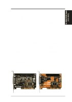
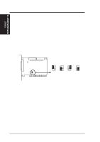
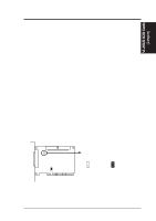
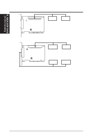
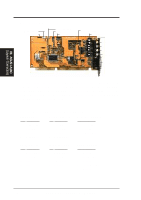
VII. ASUS I-A16C (Layout / Connectors) VII. ASUS I-A16C Audio Card Layout and Connectors Mitsumi Audio In Sony Audio In Panasonic Audio In PC Speaker In Volume Control Wave Table Upgrade PC Speaker Out Speaker Out Line Out Line In Microphone MIDI/Game Connectors The audio input connectors are used when you wish to control software mixer settings (bass, treble, volume, etc.) for audio CD's that are played with your CD-ROM. If the "Audio Out" from the CD-ROM is not connected to the "Audio In" on the card, you can only use the direct output located in the front panel of the CD-ROM and adjust volume level by the knob. CD-Audio Connector Pin Definitions Sony Audio In Pin Definition l Right Signal 2 Ground 3 Ground 4 Left Signal Mitsumi Audio In Pin Definition 1 Ground 2 Left Signal 3 Ground 4 Right Signal Panasonic Audio In Pin Definition 1 Left Signal 2 Ground 3 Right Signal -- ---- PC Speaker In Pin Definition 1 Mono Signal 2 Ground PC Speaker Out Pin Definition 1 Right Signal 2 Ground 3 Left Signal 4 Ground -- ---- Volume Control Pin Definition 1 Ground 2 Volume Up 3 Ground 4 Volume Down 5 Ground 58 ASUS P/I-P55T2P4 User's Manual
-
 1
1 -
2
-
3
-
4
-
5
-
6
-
7
-
8
-
9
-
10
-
11
-
12
-
13
-
14
-
15
-
16
-
17
-
18
-
19
-
20
-
21
-
22
-
23
-
24
-
25
-
26
-
27
-
28
-
29
-
30
-
31
-
32
-
33
-
34
-
35
-
36
-
37
-
38
-
39
-
40
-
41
-
42
-
43
-
44
-
45
-
46
-
47
-
48
-
49
-
50
-
51
-
52
-
53
-
54
-
55
-
56
-
57
-
58
-
 59
59 -
 60
60 -
 61
61 -
 62
62 -
 63
63 -
 64
64
 |
 |
