Asus P4V800-X P4V800-X User Manual - Page 33
Chassis intrusion connector 4-1 pin CHASSIS1, System panel connector 20-pin PANEL1, System Power LED
 |
View all Asus P4V800-X manuals
Add to My Manuals
Save this manual to your list of manuals |
Page 33 highlights
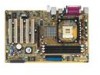
10. Chassis intrusion connector (4-1 pin CHASSIS1) This lead is for a chassis designed with intrusion detection feature. This requires an external detection mechanism such as a chassis intrusion sensor or microswitch. When you remove any chassis component, the sensor triggers and sends a high-level signal to this lead to record a chassis intrusion event. By default, the pins labeled "Chassis Signal" and "Ground" are shorted with a jumper cap. If you wish to use the chassis intrusion detection feature, remove the jumper cap from the pins. CHASSIS1 +5VSB_MB Chassis Signal GND ® P4V800-X P4V800-X Chassis Alarm Lead (Default) 11. System panel connector (20-pin PANEL1) This connector accommodates several system front panel functions. Power LED Speaker Connector PLED+ PLED+5V Ground Ground Speaker IDE_LED+ IDE_LED- ExtSMI# Ground PWR Ground Reset Ground P4V800-X IDE_LED SMI Lead Reset SW ATX Power Switch* * Requires an ATX power supply. P4V800-X System Panel Connector • System Power LED Lead (3-1 pin PLED) This 3-1 pin connector connects to the system power LED. The LED lights up when you turn on the system power, and blinks when the system is in sleep mode. • System Warning Speaker Lead (4-pin SPKR) This 4-pin connector connects to the case-mounted speaker and allows you to hear system beeps and warnings. ASUS P4V800-X motherboard user guide 1-23
-
 1
1 -
2
-
3
-
4
-
5
-
6
-
7
-
8
-
9
-
10
-
11
-
12
-
13
-
14
-
15
-
16
-
17
-
18
-
19
-
20
-
21
-
22
-
23
-
24
-
25
-
26
-
27
-
 28
28 -
 29
29 -
 30
30 -
 31
31 -
 32
32 -
 33
33 -
 34
34 -
 35
35 -
 36
36 -
 37
37 -
 38
38 -
39
-
40
-
41
-
42
-
43
-
44
-
45
-
46
-
47
-
48
-
49
-
50
-
51
-
52
-
53
-
54
-
55
-
56
-
57
-
58
-
59
-
60
-
61
-
62
-
63
-
64
-
65
-
66
-
67
-
68
-
69
-
70
-
71
-
72
-
73
-
74
 |
 |
