Asus P5B SE User Manual - Page 48
Digital audio connector 4-1 pin SPDIF_OUT, JMicron JMB363, Serial ATA RAID connector 7-pin SATA_E1 - p5b serial port
 |
UPC - 610839154968
View all Asus P5B SE manuals
Add to My Manuals
Save this manual to your list of manuals |
Page 48 highlights
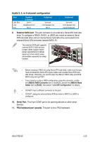
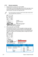
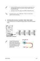
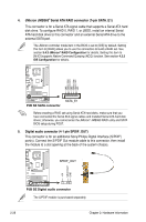
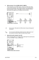
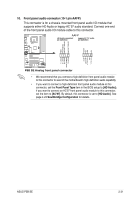
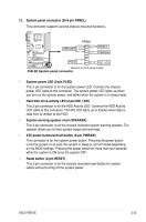
4. JMicron JMB363® Serial ATA RAID connector (7-pin SATA_E1) This connector is for a Serial ATA signal cable that supports a Serial ATA hard disk drive. To configure RAID 0, RAID 1, or JBOD, install an internal Serial ATA hard disk drive to this connector and an external Serial ATA drive to the external SATA port. The JMicron controller mode item in the BIOS is set to [IDE] by default. Setting this item to [RAID] allows you to use the connectors to build a RAID set. See section 5.4.3 JMicron® RAID Configuration for details. Setting this item to [AHCI] supports Native Command Queuing (NCQ) function. See section 4.3.5 IDE Configuration for details. ® GND RSATA_RXN2 RSATA_RXP2 GND RSATA_TXN2 RSATA_TXP2 GND P5B SE P5B SE SATA connector SATA_E1 Before creating a RAID set using Serial ATA hard disks, make sure that you have connected the Serial ATA signal cables and installed Serial ATA hard disk drives; otherwise, you cannot enter the JMicron® JMB363 RAID utility and SATA BIOS setup during POST. 5. Digital audio connector (4-1 pin SPDIF_OUT) This connector is for an additional Sony/Philips Digital Interface (S/PDIF) port(s). Connect the S/PDIF Out module cable to this connector, then install the module to a slot opening at the back of the system chassis. SPDIF_OUT P5B SE ® +5V SPDIFOUT GND P5B SE Digital audio connector The S/PDIF module is purchased separately. 2-28 Chapter 2: Hardware information
-
 1
1 -
2
-
3
-
4
-
5
-
6
-
7
-
8
-
9
-
10
-
11
-
12
-
13
-
14
-
15
-
16
-
17
-
18
-
19
-
20
-
21
-
22
-
23
-
24
-
25
-
26
-
27
-
28
-
29
-
30
-
31
-
32
-
33
-
34
-
35
-
36
-
37
-
38
-
39
-
40
-
41
-
42
-
 43
43 -
 44
44 -
 45
45 -
 46
46 -
 47
47 -
 48
48 -
 49
49 -
 50
50 -
 51
51 -
 52
52 -
 53
53 -
54
-
55
-
56
-
57
-
58
-
59
-
60
-
61
-
62
-
63
-
64
-
65
-
66
-
67
-
68
-
69
-
70
-
71
-
72
-
73
-
74
-
75
-
76
-
77
-
78
-
79
-
80
-
81
-
82
-
83
-
84
-
85
-
86
-
87
-
88
-
89
-
90
-
91
-
92
-
93
-
94
-
95
-
96
-
97
-
98
-
99
-
100
-
101
-
102
-
103
-
104
-
105
-
106
-
107
-
108
-
109
-
110
-
111
-
112
-
113
-
114
-
115
-
116
-
117
-
118
-
119
-
120
-
121
-
122
-
123
-
124
-
125
-
126
-
127
-
128
-
129
-
130
-
131
-
132
-
133
-
134
-
135
-
136
 |
 |
