Asus P5KPL SE User Manual
Asus P5KPL SE Manual
 |
View all Asus P5KPL SE manuals
Add to My Manuals
Save this manual to your list of manuals |
Asus P5KPL SE manual content summary:
- Asus P5KPL SE | User Manual - Page 1
P5KPL SE Motherboard - Asus P5KPL SE | User Manual - Page 2
without the express written permission of ASUSTeK Computer Inc. ("ASUS"). Product warranty or service will not be extended if: ASUS HAS BEEN ADVISED OF THE POSSIBILITY OF SUCH DAMAGES ARISING FROM ANY DEFECT OR ERROR IN THIS MANUAL OR PRODUCT. SPECIFICATIONS AND INFORMATION CONTAINED IN THIS MANUAL - Asus P5KPL SE | User Manual - Page 3
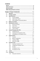
vii P5KPL SE specifications summary ix Chapter 1Product introduction 1-1 1.1 Welcome 1-1 1.2 Package contents 1-1 1.3 Special features 1-1 1.3.1 Product highlights 1-1 1.3.2 ASUS unique features 1-2 1.3.3 ASUS Intelligent Overclocking features 1-3 1.4 Before you proceed 1-4 1.5 Motherboard - Asus P5KPL SE | User Manual - Page 4
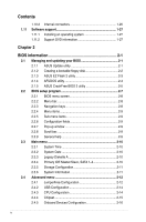
1.11.2 Support DVD information 1-27 Chapter 2 BIOS information 2-1 2.1 Managing and updating your BIOS 2-1 2.1.1 ASUS Update utility 2-1 2.1.2 Creating a bootable floppy disk 2-2 2.1.3 ASUS EZ Flash 2 utility 2-3 2.1.4 AFUDOS utility 2-4 2.1.5 ASUS CrashFree BIOS 3 utility 2-5 2.2 BIOS setup - Asus P5KPL SE | User Manual - Page 5
Mode 2-17 2.5.2 ACPI 2.0 Support 2-17 2.5.3 ACPI APIC Support 2-18 2.5.4 APM Configuration 2-18 2.5.5 Hardware Monitor 2-18 2.6 Boot menu 2-19 2.6.1 Boot Device Priority 2-19 2.6.2 Boot Settings Configuration 2-19 2.6.3 Security 2-20 2.7 Tools menu 2-21 2.7.1 ASUS EZ Flash 2 2-21 2.7.2 AI - Asus P5KPL SE | User Manual - Page 6
and used in accordance with manufacturer's instructions, may cause harmful interference to radio communications set out in the Radio Interference Regulations of the Canadian Department of Communications. This class B digital apparatus complies with Canadian ICES-003. DO NOT throw the motherboard - Asus P5KPL SE | User Manual - Page 7
. How this guide is organized This guide contains the following parts: • Chapter 1: Product introduction This chapter describes the features of the motherboard and the new technology it supports. • Chapter 2: BIOS setup This chapter tells how to change system settings through the BIOS Setup menus - Asus P5KPL SE | User Manual - Page 8
updates. 1. ASUS websites The ASUS website provides updated information on ASUS hardware and software products. Refer to the ASUS contact used in this guide To make sure that you perform certain tasks properly, take note of the following symbols used throughout this manual. DANGER/WARNING: - Asus P5KPL SE | User Manual - Page 9
P5KPL SE specifications summary CPU. Chipset Front Side Bus Memory Expansion Slots Storage LAN ASUS Overclocking Features LGA775 socket for Intel® Core™2 Quad/Core™2 Extreme/Core™2 Duo/Pentium® Extreme/Pentium® D/Pentium® 4/Celeron® Sequence Processors Intel® Hyper-Threading Technology ready - Asus P5KPL SE | User Manual - Page 10
P5KPL SE specifications summary Rear panel Internal connectors Audio USB BIOS features Manageability Supported OS Support DVD contents Accessories Form factor 1 x PS/2 keyboard port 1 x PS/2 mouse port 1 x Parallel port 1 x COM 1 x LAN (RJ-45) port 4 x USB 2.0 ports 6-channel audio 2 x USB 2.0 - Asus P5KPL SE | User Manual - Page 11
contents Check your motherboard package for the following items. Motherboard Cables Accessories Application DVD Documentation ASUS P5KPL SE motherboard 1 x Serial ATA cable 1 x Ultra DMA 100/66 cable 1 x SATA power cable 1 x I/O shield ASUS motherboard support DVD User Manual If any of - Asus P5KPL SE | User Manual - Page 12
technology and 1600 (overclocking)/1333/1066/800 MHz FSB, Intel® Core™2 processor is designed to provide powerful and energy efficient performance. Serial ATA 3Gb/s technology This motherboard supports hard drives based on the Serial ATA (SATA) 3Gb/s storage specifications, delivering enhanced - Asus P5KPL SE | User Manual - Page 13
due to overclocking failure. When the system hangs due to overclocking failure, C.P.R. eliminates the need to open the system chassis and clear the RTC data. Simply shut down and reboot the system, and the BIOS automatically restores the CPU default settings for each parameter. ASUS P5KPL SE 1-3 - Asus P5KPL SE | User Manual - Page 14
Take note of the following precautions before you install motherboard components or change any motherboard settings. • Unplug the power cord from the wall plugging in any motherboard component. The illustration below shows the location of the onboard LED. P5KPL SE SB_PWR P5KPL SE Onboard LED ON - Asus P5KPL SE | User Manual - Page 15
as indicated in the image below. 1.5.2 Screw holes Place six screws into the holes indicated by circles to secure the motherboard to the chassis. Do not overtighten the screws! Doing so can damage the motherboard. Place this side towards. the rear of the chassis P5KPL SE ASUS P5KPL SE 1-5 - Asus P5KPL SE | User Manual - Page 16
30.5cm(12in) LAN1_USB12 Intel® ICS G31 B0 9LPRS954A3GLF 6 AUDIO EATXPWR PRI_IDE PCIEX1_1 1 PCIEX16 RTL 8111C P5KPL SE PCIEX1_2 7 PCIEX1_3 SPEAKER Intel® ICH7 PCI1 USB56 SATA1 SATA3 SATA2 SATA4 ALC662 CD AAFP SPDIF_OUT 15 14 13 PCI2 PCI3 8Mb BIOS Lithium Cell CMOS Power - Asus P5KPL SE | User Manual - Page 17
Merchandise Authorization (RMA) requests only if the motherboard comes with the cap on the LGA775 socket. • The product warranty does not cover damage to the socket contacts resulting from incorrect CPU installation/removal, or misplacement/loss/incorrect removal of the PnP cap. ASUS P5KPL SE 1-7 - Asus P5KPL SE | User Manual - Page 18
1.6.1 Installing the CPU To install a CPU: 1. Locate the CPU socket on the motherboard. P5KPL SE P5KPL SE CPU socket 775 Before installing the CPU, ensure that push the PnP cap from the load plate window to remove (4B). Retention tab A B Load lever PnP cap Load plate 4B 4A 3 1-8 - Asus P5KPL SE | User Manual - Page 19
CPU notch. CPU notch Gold triangle mark Alignment key 6. Apply several drops of Thermal Interface Material to the exposed area of the CPU that motherboard supports Intel® LGA775 processors with the Intel® Enhanced Intel SpeedStep® Technology (EIST) and HyperThreading Technology. B ASUS P5KPL SE - Asus P5KPL SE | User Manual - Page 20
to the connector on the motherboard labeled CPU_FAN. CPU_FAN CPU FAN PWM CPU FAN IN CPU FAN PWR GND Do not forget to connect the CPU fan connector! Hardware monitoring errors can occur if you fail to plug this connector. P5KPL SE P5KPL SE CPU fan connector 1-10 Chapter 1: Product introduction - Asus P5KPL SE | User Manual - Page 21
The motherboard comes with two Double Data Rate 2 (DDR2) Dual Inline Memory Modules (DIMM) sockets. The figure illustrates the location of the DDR2 DIMM sockets: DIMM_A1 DIMM_B1 P5KPL SE P5KPL SE 240-pin DDR2 DIMM sockets Channel Channel A Channel B Sockets DIMM_A1 DIMM_B1 ASUS P5KPL SE 1-11 - Asus P5KPL SE | User Manual - Page 22
support DIMMs made up of 256 megabit (Mb) chips or less. Some old-version DDR2-800 DIMMs may not match Intel® On-Die-Termination (ODT) requirement and will automatically downgrade to run at DDR-667. If this heppens, contact your memory vendor to check to ODT value. P5KPL SE Motherboard Qualified - Asus P5KPL SE | User Manual - Page 23
-Y5 NT5TU64M8AE-3C EPD264082200-4 EPD264082200-4 DIMM support · · · · · · · · · · · · · · · · · · · · · · · · · · · · · · · · · · · · · · · · · · · · · · · · · · · · · · · · · · · · · · · · · · · · · · · · · ASUS P5KPL SE 1-13 - Asus P5KPL SE | User Manual - Page 24
-8E1 5 PSC 2G AENEON AET860UD00-25DC08X 5 AENEON 2G G.SKILL F2-6400CL5D-4GBPQ 5 G.SKILL SS/ DS Component DIMM support A* B* SS K4T51083QC-ZCE7 · · SS V59C1512804QBF25S0054707PEBPA · · DS K4T51083QC-ZCE7 · · DS Heat-Sink Package · · DS NT5TU64M8BE-25C62321800CP · · DS Heat - Asus P5KPL SE | User Manual - Page 25
A*: Supports one module inserted into any slot as Single-channel memory configuration. • B*: Supports one pair of modules inserted into both the yellow slots as one pair of Dual-channel memory configuration. Visit the ASUS website for the latest DDR2-667/800/1066MHz QVL. ASUS P5KPL SE 1-15 - Asus P5KPL SE | User Manual - Page 26
components. Failure to do so can cause severe damage to both the motherboard and the components. 1. Unlock a DDR2 DIMM socket by pressing the 1. Simultaneously press the retaining clips outward to unlock the DIMM. Support the DIMM lightly with your fingers when pressing the retaining clips. - Asus P5KPL SE | User Manual - Page 27
x1 slot This motherboard supports PCI Express x1 network cards, SCSI cards and other cards that comply with the PCI Express specifications. 1.8.6 PCI Express x16 slot This motherboard supports a PCI Express x16 graphics card that complies with the PCI Express specifications. ASUS P5KPL SE 1-17 - Asus P5KPL SE | User Manual - Page 28
, then the BIOS automatically resets parameter settings to default values. • Due to the chipset limitation, AC power off is required before you use the C.P.R. function. You must turn off and on the power supply or unplug and plug the power cord before rebooting the system. P5KPL SE CLRTC 12 23 - Asus P5KPL SE | User Manual - Page 29
of the audio ports in 2, 4, or 6-channel configuration. Audio 2, 4, or 6-channel configuration Port Light Blue Lime Pink Headset 2-channel Line In Line Out Mic In 4-channel Rear Speaker Out Front Speaker Out Mic In 6-channel Rear Speaker Out Front Speaker Out Bass/Center ASUS P5KPL SE 1-19 - Asus P5KPL SE | User Manual - Page 30
USB) ports are available for connecting USB 2.0 devices. 8. USB 2.0 ports 3 and 4. These two 4-pin Universal Serial Bus (USB) ports are available for connecting USB separately. FLOPPY PIN1 P5KPL SE NOTE:Orient the red markings on the floppy ribbon cable to PIN 1. P5KPL SE Floppy disk drive - Asus P5KPL SE | User Manual - Page 31
to the motherboard's IDE connector, then select one of the following modes to configure your device. Single device Two devices Drive jumper setting Cable- same setting. PIN1 P5KPL SE NOTE:Orient the red markings on the IDE ribbon cable to PIN 1. P5KPL SE IDE connector 4. Digital audio connector - Asus P5KPL SE | User Manual - Page 32
SATA4 P5KPL SE GND RSATA_RXN1 RSATA_RXP1 GND RSATA_TXN1 RSATA_TXP1 GND P5KPL SE SATA motherboard components. This is not a jumper! Do not place jumper cap on the fan connector! CPU_FAN CPU FAN PWM CPU FAN IN CPU FAN PWR GND P5KPL SE P5KPL SE CPU fan connector Only the CPU fan supports the ASUS - Asus P5KPL SE | User Manual - Page 33
damage the motherboard! The USB module cable is purchased separately. 8. Optical drive audio connector (4-pin CD) These connectors allow you to receive stereo audio input from sound sources such as a CD-ROM, TV tuner, or MPEG card. CD P5KPL SE P5KPL SE Internal audio connector Right Audio Channel - Asus P5KPL SE | User Manual - Page 34
pin definition compliant definition P5KPL SE Analog front panel connector • We recommend that you connect a high-definition front panel audio module to this connector to avail of the motherboard's high-definition audio capability. • By default, this connector is set to HD Audio. If you want to - Asus P5KPL SE | User Manual - Page 35
system, refer to the Recommended Power Supply Wattage Calculator at http://support.asus. com/PowerSupplyCalculator/PSCalculator.aspx?SLanguage=en-us for details. • The ATX 12 V Specification 2.0-compliant (400W) PSU has been tested to support the motherboard power requirements. ASUS P5KPL SE 1-25 - Asus P5KPL SE | User Manual - Page 36
supports several chassis-mounted functions. PWR LED PWR BTN PLED+ PLEDPWR GND P5KPL SE F_PANEL PIN 1 IDE_LED+ IDE_LED- Ground Reset HD_LED RESET P5KPL SE puts the system in sleep or soft-off mode depending on the BIOS settings. Pressing the power switch for more than four seconds while the - Asus P5KPL SE | User Manual - Page 37
1.11.1 Installing an operating system This motherboard supports Windows® XP/Vista Operating Systems (OS). Always install the latest OS version and corresponding updates to maximize the features of your hardware. • Motherboard settings and hardware options vary. Use the setup procedures presented - Asus P5KPL SE | User Manual - Page 38
1-28 Chapter 1: Product introduction - Asus P5KPL SE | User Manual - Page 39
install ASUS Update: 1. Place the support DVD in the optical drive. The Drivers menu appears. 2. Click the Utilities tab, then click Install ASUS Update. 3. The ASUS Update utility is copied to your system. Quit all Windows® applications before you update the BIOS using this utility. ASUS P5KPL SE - Asus P5KPL SE | User Manual - Page 40
to download then click Next. 5. Follow the screen instructions to complete the update process. The ASUS Update utility is capable of updating itself through the Internet. Always update the utility to avail all its features. Updating the BIOS through a BIOS file To update the BIOS through a BIOS - Asus P5KPL SE | User Manual - Page 41
update process and automatically reboots the system when done. • This function can support devices such as USB flash disk, or floppy disk with FAT 32/16 format and single partition only. • Do not shut down or reset the system while updating the BIOS to prevent system boot failure! ASUS P5KPL SE - Asus P5KPL SE | User Manual - Page 42
returns to the DOS prompt after copying the current BIOS file. Updating the BIOS file To update the BIOS file using the AFUDOS utility: 1. Visit the ASUS website (www.asus.com) and download the latest BIOS file for the motherboard. Save the BIOS file to a bootable floppy disk. We recommend that you - Asus P5KPL SE | User Manual - Page 43
flashing the corrupted BIOS file. Bad BIOS checksum. Starting BIOS recovery... Checking for floppy... Floppy found! Reading file "P5KPLSE.ROM". Completed. Start flashing... DO NOT shut down or reset the system while updating the BIOS! Doing so can cause system boot failure! ASUS P5KPL SE 2-5 - Asus P5KPL SE | User Manual - Page 44
"P5KPLSE.ROM". Completed. Start flashing... 4. Restart the system after the utility completes the updating process. The recovered BIOS may not be the latest BIOS version for this motherboard. Visit the ASUS website (www.asus.com) to download the latest BIOS file. Recovering the BIOS from a USB flash - Asus P5KPL SE | User Manual - Page 45
under the Exit Menu. See section 2.8 Exit Menu. • The BIOS setup screens shown in this section are for reference purposes only, and may not exactly match what you see on your screen. • Visit the ASUS website at www.asus.com to download the latest BIOS file for this motherboard. ASUS P5KPL SE 2-7 - Asus P5KPL SE | User Manual - Page 46
BIOS SETUP UTILITY Advanced Power Boot Tools General help Exit System Time [14:14:35] System Date [Wed 04/16/2008] Legacy Diskette A [1.44M, 3.5 in.] Primary IDE Master :[Not Detected] Primary IDE Slave :[Not Detected] SATA 1 :[Not Detected] SATA 2 :[Not Detected] SATA settings. - Asus P5KPL SE | User Manual - Page 47
Help F10 Save and Exit ESC Exit v02.61 (C)Copyright 1985- 2 0 0 8 , A m e r i c a n Megatrends, Inc. Pop-up window Scroll bar display the other items on the screen. 2.2.9 General help At the top right corner of the menu screen is a brief description of the selected item. ASUS P5KPL SE 2-9 - Asus P5KPL SE | User Manual - Page 48
Diskette A [1.44M, 3.5 in.] Sets the type of floppy drive installed. Configuration options: [Disabled] [360K, 5.25 in] [1.2M, 5.25 in] [720K, 3.5 in.] [1.44M, 3.5 in.] [2.88M, 3.5 in] 2.3.4 Primary IDE Master/Slave, SATA 1~4 While entering Setup, the BIOS automatically detects the presence of IDE - Asus P5KPL SE | User Manual - Page 49
The items in this menu allow you to set or change the configurations for the SATA devices installed in the system. Select an item system specifications. The BIOS automatically detects the items in this menu. Bios Information Displays the auto-detected BIOS information. ASUS P5KPL SE 2-11 - Asus P5KPL SE | User Manual - Page 50
item appears only when you set the AI Overclocking item to [Manual]. CPU Frequency [XXX] Displays the frequency sent by the clock generator to the system bus and PCI bus. The value of this item is auto-detected by the BIOS. Use the and keys to adjust the CPU frequency. You can also type - Asus P5KPL SE | User Manual - Page 51
] Allows you to select ICH chipset voltage or set it to [Auto] for safe mode. Configuration options: [Auto] [1.5V] [1.6V] VCore Over Voltage [Auto] Allows you to select VCore over voltage or set it to [Auto] for safe mode. Configuration options: [Auto] [+50mv] [+100mv] [+150mv] ASUS P5KPL SE 2-13 - Asus P5KPL SE | User Manual - Page 52
] Allows you to configure the USB 2.0 controller in HiSpeed (480 Mbps) or Full Speed (12 Mbps). Configuration options: [FullSpeed] [HiSpeed] 2.4.3 CPU Configuration The items in this menu show the CPU-related information that the BIOS automatically detects. CPU Ratio Setting [Auto] Allows you to - Asus P5KPL SE | User Manual - Page 53
Intel® Pentium® 4 or later CPU that supports the Enhanced Intel SpeedStep® Technology (EIST). Intel (R) SpeedStep Technology [Enabled] Allows you to use the Enhanced Intel® SpeedStep® Technology. When set or disable the PEG Force x1. Configuration options: [Enabled] [Disabled] ASUS P5KPL SE 2-15 - Asus P5KPL SE | User Manual - Page 54
: [Azalia] [Disabled] Front Panel Support Type [HD Audio] Allows you to select the front panel support type. If High Definition Audio Front Panel used, please set HD Audio mode. Configuration options: [AC97] [HD Audio] 2.4.5 Onboard Devices Configuration Onboard PCIE GbE LAN [Enabled] Allows you to - Asus P5KPL SE | User Manual - Page 55
system resumes to its working state exactly where it was left off. [Auto] - Detected by OS. 2.5.2 ACPI 2.0 Support [Disabled] Allows you to add more tables for Advanced Configuration and Power Interface (ACPI) 2.0 specifications. Configuration options: [Disabled] [Enabled] ASUS P5KPL SE 2-17 - Asus P5KPL SE | User Manual - Page 56
support in the Application-Specific Integrated Circuit (ASIC). When set set to Power On, the system goes on after an AC power loss. When set set use specific Disabled] When set to [ CPU/MB Temperature [xxxºC/xxxºF]. The onboard hardware monitor automatically detects and displays the CPU/ motherboard - Asus P5KPL SE | User Manual - Page 57
BIOS performs all the POST items. Configuration options: [Disabled] [Enabled] Full Screen Logo [Enabled] This allows you to enable or disable the full screen logo display feature. Configuration options: [Disabled] [Enabled] Set this item to [Enabled] to use the ASUS MyLogo2™ feature. ASUS P5KPL SE - Asus P5KPL SE | User Manual - Page 58
Enter>. The message "Password Uninstalled" appears. If you forget your BIOS password, you can clear it by erasing the CMOS Real Time Clock (RTC) RAM. See section "1.9 Jumper" for information on how to erase the RTC RAM. After you have set a supervisor password, the other items appear to allow you to - Asus P5KPL SE | User Manual - Page 59
Allows you to run ASUS EZ Flash 2. When you press , a confirmation message appears. Use the left/right arrow key to select between [Yes] or [No], then press to confirm your choice. Please see section 2.1.3 for details. This function only supports FAT 32/16 format. ASUS P5KPL SE 2-21 - Asus P5KPL SE | User Manual - Page 60
Exit menu to ensure the values you selected are saved to the CMOS RAM. An onboard backup battery sustains the CMOS RAM so it stays on even when the PC is turned off. When you select this option, a confirmation window appears. Select OK to save changes and exit. Exit & Discard Changes Select this
-
 1
1 -
 2
2 -
 3
3 -
 4
4 -
 5
5 -
 6
6 -
 7
7 -
8
-
9
-
10
-
11
-
12
-
13
-
14
-
15
-
16
-
17
-
18
-
19
-
20
-
21
-
22
-
23
-
24
-
25
-
26
-
27
-
28
-
29
-
30
-
31
-
32
-
33
-
34
-
35
-
36
-
37
-
38
-
39
-
40
-
41
-
42
-
43
-
44
-
45
-
46
-
47
-
48
-
49
-
50
-
51
-
52
-
53
-
54
-
55
-
56
-
57
-
58
-
59
-
60
 |
 |

Motherboard
P5KPL SE