Asus P5KPL SE User Manual - Page 31
P5KPL SE IDE connector
 |
View all Asus P5KPL SE manuals
Add to My Manuals
Save this manual to your list of manuals |
Page 31 highlights
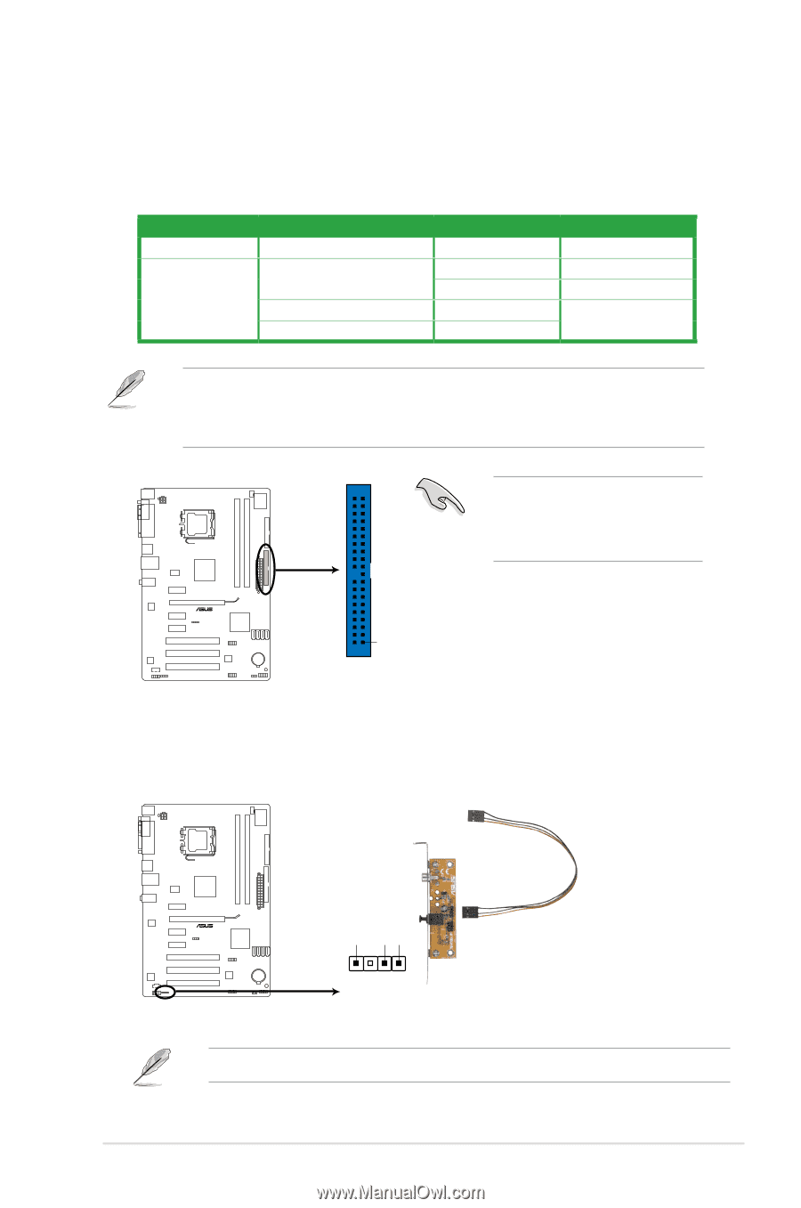
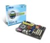
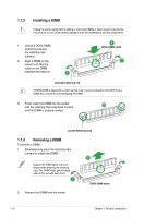
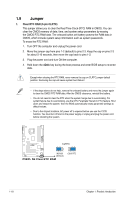
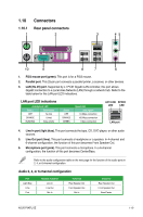
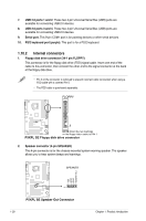
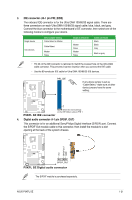
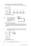
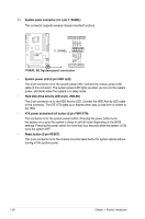
3. IDE connector (40-1 pin PRI_EIDE) The onboard IDE connector is for the Ultra DMA 100/66/33 signal cable. There are three connectors on each Ultra DMA 100/66/33 signal cable: blue, black, and gray. Connect the blue connector to the motherboard's IDE connector, then select one of the following modes to configure your device. Single device Two devices Drive jumper setting Cable-Select or Master Cable-Select Master Slave Mode of device(s) Master Slave Master Slave Cable connector Black Black Gray Black or gray • Pin 20 on the IDE connector is removed to match the covered hole on the Ultra DMA cable connector. This prevents incorrect insertion when you connect the IDE cable. • Use the 80-conductor IDE cable for Ultra DMA 100/66/33 IDE devices. PRI_IDE If any device jumper is set as "Cable-Select," make sure all other device jumpers have the same setting. PIN1 P5KPL SE NOTE:Orient the red markings on the IDE ribbon cable to PIN 1. P5KPL SE IDE connector 4. Digital audio connector (4-1 pin SPDIF_OUT) This connector is for an additional Sony/Philips Digital Interface (S/PDIF) port. Connect the S/PDIF Out module cable to this connector, then install the module to a slot opening at the back of the system chassis. SPDIFOUT GND +5V P5KPL SE SPDIF_OUT P5KPL SE Digital audio connector The S/PDIF module is purchased separately. ASUS P5KPL SE 1-21
-
 1
1 -
2
-
3
-
4
-
5
-
6
-
7
-
8
-
9
-
10
-
11
-
12
-
13
-
14
-
15
-
16
-
17
-
18
-
19
-
20
-
21
-
22
-
23
-
24
-
25
-
 26
26 -
 27
27 -
 28
28 -
 29
29 -
 30
30 -
 31
31 -
 32
32 -
 33
33 -
 34
34 -
 35
35 -
 36
36 -
37
-
38
-
39
-
40
-
41
-
42
-
43
-
44
-
45
-
46
-
47
-
48
-
49
-
50
-
51
-
52
-
53
-
54
-
55
-
56
-
57
-
58
-
59
-
60
 |
 |