Asus P5KPL SE User Manual - Page 30
Internal connectors
 |
View all Asus P5KPL SE manuals
Add to My Manuals
Save this manual to your list of manuals |
Page 30 highlights
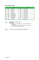
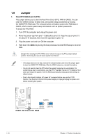
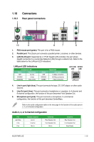
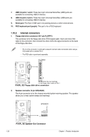
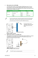
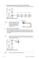
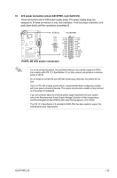
7. USB 2.0 ports 1 and 2. These two 4-pin Universal Serial Bus (USB) ports are available for connecting USB 2.0 devices. 8. USB 2.0 ports 3 and 4. These two 4-pin Universal Serial Bus (USB) ports are available for connecting USB 2.0 devices. 9. Serial port. This 9-pin COM1 port is for pointing devices or other serial devices. 10. PS/2 keyboard port (purple). This port is for a PS/2 keyboard. 1.10.2 Internal connectors 1. Floppy disk drive connector (34-1 pin FLOPPY) This connector is for the floppy disk drive (FDD) signal cable. Insert one end of the cable to this connector, then connect the other end to the signal connector at the back of the floppy disk drive. • Pin 5 on the connector is removed to prevent incorrect cable connection when using a FDD cable with a covered Pin 5. • The FDD cable is purchased separately. FLOPPY PIN1 P5KPL SE NOTE:Orient the red markings on the floppy ribbon cable to PIN 1. P5KPL SE Floppy disk drive connector 2. Speaker connector (4-pin SPEAKER) This 4-pin connector is for the chassis-mounted system warning speaker. The speaker allows you to hear system beeps and warnings. SPEAKER Speaker Out GND GND +5V P5KPL SE PIN 1 P5KPL SE Speaker Out Connector 1-20 Chapter 1: Product introduction
-
 1
1 -
2
-
3
-
4
-
5
-
6
-
7
-
8
-
9
-
10
-
11
-
12
-
13
-
14
-
15
-
16
-
17
-
18
-
19
-
20
-
21
-
22
-
23
-
24
-
 25
25 -
 26
26 -
 27
27 -
 28
28 -
 29
29 -
 30
30 -
 31
31 -
 32
32 -
 33
33 -
 34
34 -
 35
35 -
36
-
37
-
38
-
39
-
40
-
41
-
42
-
43
-
44
-
45
-
46
-
47
-
48
-
49
-
50
-
51
-
52
-
53
-
54
-
55
-
56
-
57
-
58
-
59
-
60
 |
 |
