Asus P5PEVM Motherboard Installation Guide - Page 42
Power/Soft-off button 2-pin PWRSW
 |
View all Asus P5PEVM manuals
Add to My Manuals
Save this manual to your list of manuals |
Page 42 highlights
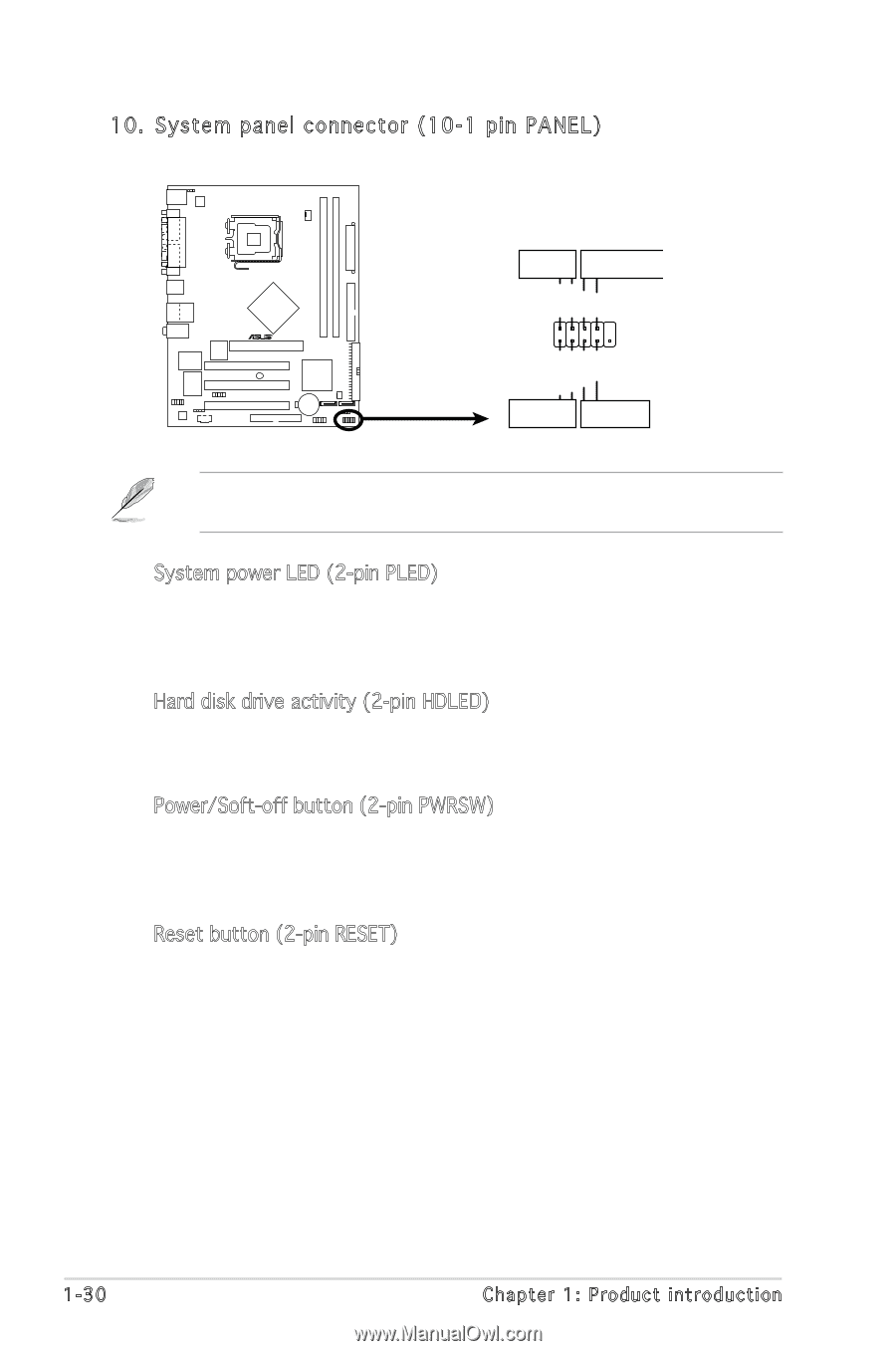
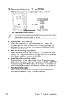
10. System panel connector (10-1 pin PANEL) This connector supports several chassis-mounted functions. P5PE-VM PLED PWRSW PLED+ PLEDPWR GND R F_PANEL IDELED+ IDELED- Ground Reset P5PE-VM System Panel Connector HDLED RESET The sytem panel connector is color-coded for easy connection. Refer to the connector description below for details. • System power LED (2-pin PLED) This 2-pin connector is for the system power LED. Connect the chassis power LED cable to this connector. The system power LED lights up when you turn on the system power, and blinks when the system is in sleep mode. • Hard disk drive activity (2-pin HDLED) This 2-pin connector is for the HDD Activity LED. Connect the HDD Activity LED cable to this connector. The IDE LED lights up or flashes when data is read from or written to the HDD. • Power/Soft-off button (2-pin PWRSW) This connector is for the system power button. Pressing the power button turns the system ON or puts the system in SLEEP or SOFT-OFF mode depending on the BIOS settings. Pressing the power switch for more than four seconds while the system is ON turns the system OFF. • Reset button (2-pin RESET) This 2-pin connector is for the chassis-mounted reset button for system reboot without turning off the system power. 1-30 Chapter 1: Product introduction
-
 1
1 -
2
-
3
-
4
-
5
-
6
-
7
-
8
-
9
-
10
-
11
-
12
-
13
-
14
-
15
-
16
-
17
-
18
-
19
-
20
-
21
-
22
-
23
-
24
-
25
-
26
-
27
-
28
-
29
-
30
-
31
-
32
-
33
-
34
-
35
-
36
-
 37
37 -
 38
38 -
 39
39 -
 40
40 -
 41
41 -
 42
42 -
 43
43 -
 44
44 -
 45
45 -
 46
46 -
 47
47 -
48
-
49
-
50
-
51
-
52
-
53
-
54
-
55
-
56
-
57
-
58
-
59
-
60
-
61
-
62
-
63
-
64
-
65
-
66
-
67
-
68
-
69
-
70
-
71
-
72
-
73
-
74
-
75
-
76
-
77
-
78
-
79
-
80
 |
 |