Asus RAMPAGE IV EXTREME User Manual - Page 40
Expansion slots - graphics slot
 |
View all Asus RAMPAGE IV EXTREME manuals
Add to My Manuals
Save this manual to your list of manuals |
Page 40 highlights
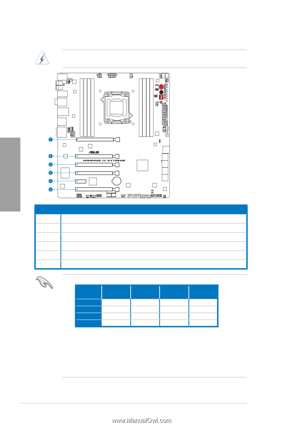
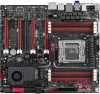
2.2.4 Expansion slots Ensure to unplug the power cord before adding or removing expansion cards. Failure to do so may cause you physical injury and damage motherboard components. Chapter 2 Slot No. Slot Description 1 PCIe 3.0 x16_1 slot 2 PCIe 3.0 x8_2A slot 3 PCIe 3.0 x8_2B slot 4 PCIe 3.0 x16/8_3 slot 5 PCIe 2.0 x1_1 slot 6 PCIe 3.0 x8_4 slot • Refer to the following configuration table for installation. PCIe x16 Slot # 1 2 4 6 Single VGA x16 - - - SLI/CF x16 - x16 - 3 way SLI/CFX x16 x8 x16 - Quad SLI/CFX x16 x8 x8 x8 • We recommend that you provide sufficient power when running CrossFireX™ or SLI mode. See page 2-32 for details. • While running at heavy loaded four VGA cards, ensure to plug in the 6-pin extra PCIe power supply for stability. • Connect a chassis fan to the motherboard connector labeled CHA_FAN1/2/3 when using multiple graphics cards for better thermal environment. 2-16 Chapter 2: Hardware information
-
 1
1 -
2
-
3
-
4
-
5
-
6
-
7
-
8
-
9
-
10
-
11
-
12
-
13
-
14
-
15
-
16
-
17
-
18
-
19
-
20
-
21
-
22
-
23
-
24
-
25
-
26
-
27
-
28
-
29
-
30
-
31
-
32
-
33
-
34
-
 35
35 -
 36
36 -
 37
37 -
 38
38 -
 39
39 -
 40
40 -
 41
41 -
 42
42 -
 43
43 -
 44
44 -
 45
45 -
46
-
47
-
48
-
49
-
50
-
51
-
52
-
53
-
54
-
55
-
56
-
57
-
58
-
59
-
60
-
61
-
62
-
63
-
64
-
65
-
66
-
67
-
68
-
69
-
70
-
71
-
72
-
73
-
74
-
75
-
76
-
77
-
78
-
79
-
80
-
81
-
82
-
83
-
84
-
85
-
86
-
87
-
88
-
89
-
90
-
91
-
92
-
93
-
94
-
95
-
96
-
97
-
98
-
99
-
100
-
101
-
102
-
103
-
104
-
105
-
106
-
107
-
108
-
109
-
110
-
111
-
112
-
113
-
114
-
115
-
116
-
117
-
118
-
119
-
120
-
121
-
122
-
123
-
124
-
125
-
126
-
127
-
128
-
129
-
130
-
131
-
132
-
133
-
134
-
135
-
136
-
137
-
138
-
139
-
140
-
141
-
142
-
143
-
144
-
145
-
146
-
147
-
148
-
149
-
150
-
151
-
152
-
153
-
154
-
155
-
156
-
157
-
158
-
159
-
160
-
161
-
162
-
163
-
164
-
165
-
166
-
167
-
168
-
169
-
170
-
171
-
172
-
173
-
174
-
175
-
176
-
177
-
178
-
179
 |
 |