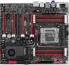
Asus RAMPAGE IV EXTREME User Manual - Page 62
Front panel audio connector 10-1 pin AAFP, ATX power connectors 24-pin EATXPWR; 4-pin EATX12V_1; 8-
 |
View all Asus RAMPAGE IV EXTREME manuals
Add to My Manuals
Save this manual to your list of manuals |
Page 62 highlights
Chapter 2 11. Front panel audio connector (10-1 pin AAFP) This connector is for a chassis-mounted front panel audio I/O module that supports either HD Audio or legacy AC`97 audio standard. Connect one end of the front panel audio I/O module cable to this connector. • We recommend that you connect a high-definition front panel audio module to this connector to avail of the motherboard's high-definition audio capability. If��y�o�u��w��a�n�t�t�o��c�o�n��n�e�c�t�a��h��ig�h��-d��e�f�in�i�ti�o�n��f�r�o�n�t�p��a�n�e�l�a��u�d�i�o��m��o�d�u�l�e��to��t�h�i�s�c��o�n�n�e��c�to��r,�s��e�t the Front Panel Type item in the BIOS setup to [HD]; if you want to connect an AC'97 front panel audio module to this connector, set the item to [AC97]. By default, this connector is set to [HD]. 12. ATX power connectors (24-pin EATXPWR; 4-pin EATX12V_1; 8-pin EATX12V_2) These connectors are for ATX power supply plugs. The power supply plugs are designed to fit these connectors in only one orientation. Find the proper orientation and push down firmly until the connectors completely fit. 2-38 Chapter 2: Hardware information
-
 1
1 -
2
-
3
-
4
-
5
-
6
-
7
-
8
-
9
-
10
-
11
-
12
-
13
-
14
-
15
-
16
-
17
-
18
-
19
-
20
-
21
-
22
-
23
-
24
-
25
-
26
-
27
-
28
-
29
-
30
-
31
-
32
-
33
-
34
-
35
-
36
-
37
-
38
-
39
-
40
-
41
-
42
-
43
-
44
-
45
-
46
-
47
-
48
-
49
-
50
-
51
-
52
-
53
-
54
-
55
-
56
-
 57
57 -
 58
58 -
 59
59 -
 60
60 -
 61
61 -
 62
62 -
 63
63 -
 64
64 -
 65
65 -
 66
66 -
 67
67 -
68
-
69
-
70
-
71
-
72
-
73
-
74
-
75
-
76
-
77
-
78
-
79
-
80
-
81
-
82
-
83
-
84
-
85
-
86
-
87
-
88
-
89
-
90
-
91
-
92
-
93
-
94
-
95
-
96
-
97
-
98
-
99
-
100
-
101
-
102
-
103
-
104
-
105
-
106
-
107
-
108
-
109
-
110
-
111
-
112
-
113
-
114
-
115
-
116
-
117
-
118
-
119
-
120
-
121
-
122
-
123
-
124
-
125
-
126
-
127
-
128
-
129
-
130
-
131
-
132
-
133
-
134
-
135
-
136
-
137
-
138
-
139
-
140
-
141
-
142
-
143
-
144
-
145
-
146
-
147
-
148
-
149
-
150
-
151
-
152
-
153
-
154
-
155
-
156
-
157
-
158
-
159
-
160
-
161
-
162
-
163
-
164
-
165
-
166
-
167
-
168
-
169
-
170
-
171
-
172
-
173
-
174
-
175
-
176
-
177
-
178
-
179
 |
 |
