Asus T2-PH1 User Guide
Asus T2-PH1 - Terminator - 0 MB RAM Manual
 |
UPC - 610839552757
View all Asus T2-PH1 manuals
Add to My Manuals
Save this manual to your list of manuals |
Asus T2-PH1 manual content summary:
- Asus T2-PH1 | User Guide - Page 1
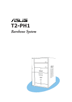
T2-PH1 Barebone System MODE - Asus T2-PH1 | User Guide - Page 2
No part of this manual, including the products and software described in it, INC. ("ASUS"). Product warranty or service will not ASUS HAS BEEN ADVISED OF THE POSSIBILITY OF SUCH DAMAGES ARISING FROM ANY DEFECT OR ERROR IN THIS MANUAL OR PRODUCT. SPECIFICATIONS AND INFORMATION CONTAINED IN THIS MANUAL - Asus T2-PH1 | User Guide - Page 3
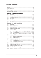
the cover 2-3 2.4 Removing the power supply 2-4 2.5 Installing a CPU 2-5 2.5.1 Removing the CPU fan and heatsink assembly ....... 2-5 2.5.2 CPU installation 2-6 2.5.3 Reinstalling the CPU fan and heatsink assembly ..... 2-9 2.6 Installing a DIMM 2-10 2.6.1 Memory configurations 2-10 2.6.2 DIMM - Asus T2-PH1 | User Guide - Page 4
system 3-2 3.2 Powering up 3-2 3.3 Support CD information 3-2 3.3.1 Running the support CD 3-3 3.3.2 Drivers menu 3-3 3.3.3 Utilities menu 3-4 3.3.4 ASUS contact information 3-6 3.3.5 Other information 3-6 3.4 Software information 3-7 3.4.1 ASUS Radio Player 3-7 3.4.2 ASUS Instant Music - Asus T2-PH1 | User Guide - Page 5
Pop-up window 5-13 5.2.8 Support 5-29 5.5.4 ACPI APIC Support 5-29 5.5.5 APM Configuration 5-30 5.5.6 Hardware Monitor 5-32 5.6 Boot menu 5-33 5.6.1 Boot Device Priority 5-33 5.6.2 Boot Settings Configuration 5-34 5.6.3 Security 5-35 5.7 Exit menu 5-37 Appendix Power supply specifications - Asus T2-PH1 | User Guide - Page 6
not installed and used in accordance with manufacturer's instructions, may cause harmful interference to radio communications. However ! The use of shielded cables for connection of the monitor to the graphics card is required to assure compliance with FCC regulations. Changes or modifications to - Asus T2-PH1 | User Guide - Page 7
cables for the devices are unplugged before the signal cables are connected. • If the power supply is broken, do not try to fix it by yourself. Contact a qualified service technician or your retailer. Operation safety • Before installing devices into the system, carefully read all the documentation - Asus T2-PH1 | User Guide - Page 8
About this guide Audience This guide provides general information and installation instructions about the ASUS T2-PH1 barebone system. This guide is intended for experienced users and integrators with hardware knowledge of personal computers. How this guide is organized This guide contains the - Asus T2-PH1 | User Guide - Page 9
T : Instructions that you MUST follow to complete a task. N O T E : Tips and additional information to aid in completing a task. Where to find more information Refer to the following sources for additional information and for product and software updates. 1. ASUS Websites The ASUS websites worldwide - Asus T2-PH1 | User Guide - Page 10
Check your T2-PH1 system package for the following items. If any of the items is damaged or missing, contact your retailer immediately. Item description 1 . A S U S T 2 - P H 1 b a r e b o n e s y s t e m with • ASUS motherboard • 250 W PFC/non-PFC power supply unit • Gigabit LAN port • CPU fan and - Asus T2-PH1 | User Guide - Page 11
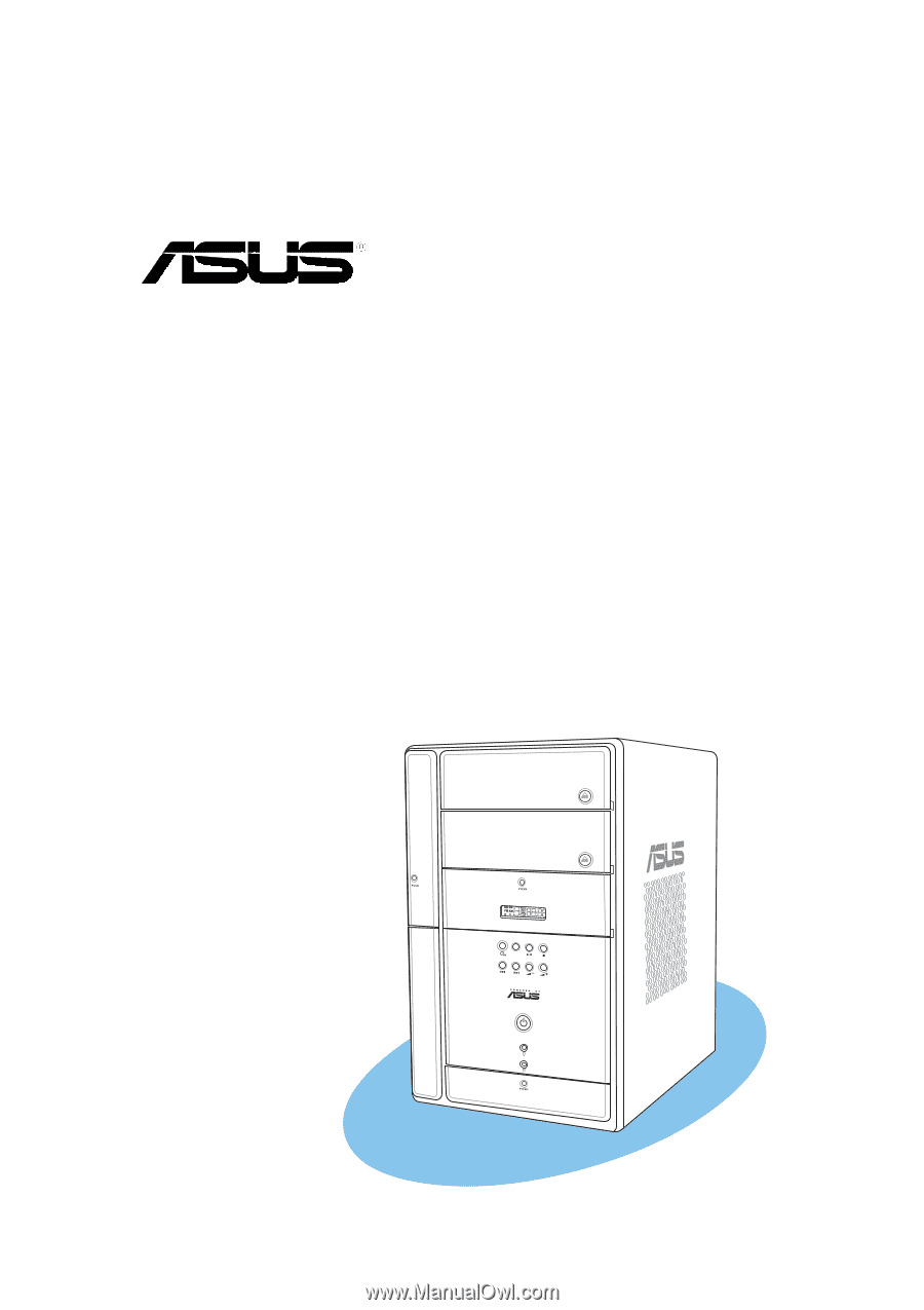
System introduction Chapter 1 This chapter gives a general description of the ASUS T2-PH1. The chapter lists the system features including introduction on the front and rear panel, and internal components. MODE ASUS T2-PH1 - Asus T2-PH1 | User Guide - Page 12
-PH1! The ASUS T2-PH1 is an all-in-one barebone system with a versatile home entertainment feature. The system comes in a stylish mini-tower casing, and powered by the ASUS motherboard that supports the Intel® Pentium® 4 processor in the 775-land package with 800 MHz FSB and up to 2 GB system memory - Asus T2-PH1 | User Guide - Page 13
e a d e r d o o r. Open this door to access the 7-in-1 storage card reader. 1 0 . L E D p a n e l. The LED panel displays the n . Press this button to put the Audio DJ function to CD mode. In Windows® mode, pressing this button shuts down, restarts, or puts the system in sleep mode ASUS T2-PH1 1-3 - Asus T2-PH1 | User Guide - Page 14
1 4 . S T O P b u t t o n . Press this button to stop the audio track being played. 1 5 . P R E V I O U S b u t t o n . Press this button to perform various functions in different modes. In C D m o d e, selects the previous audio track. In R a d i o m o d e, selects the previous preset station. 1 6 - Asus T2-PH1 | User Guide - Page 15
card. 2 4 . S m a r t M e d i a® c a r d s l o t . This slot is for a SmartMedia® storage card. • You cannot close the storage card reader door if a storage card is inserted into any of the card slots. • Use and format a storage card according to the documentation that comes with it. ASUS T2-PH1 - Asus T2-PH1 | User Guide - Page 16
p o r t . This port provides high-speed connectivity for IEEE 1394a-compliant audio/video devices, storage peripherals, and other PC devices. 2 9 . 6 - p i n I E E E 1 3 9 4 a p o r t . This port provides high-speed connectivity for IEEE 1394a-compliant audio/video devices, storage peripherals, and - Asus T2-PH1 | User Guide - Page 17
Rear panel The system rear panel includes the power connector and several I/O ports that allow convenient a l p o r t . This port connects a mouse, modem, or other devices that conforms with serial specification. 4 . P S / 2 m o u s e p o r t . This green 6-pin connector Out. ASUS T2-PH1 1-7 - Asus T2-PH1 | User Guide - Page 18
o n s l o t c o v e r s. Remove these covers when installing expansion cards. 1 4 . C h a s s i s f a n v e n t . This vent is for the PSU fan that provides ventilation inside the power supply unit. 1 7 . P o w e r c o n n e c t o r . This connector is for the power cable and plug. 1 8 . V o l t a g - Asus T2-PH1 | User Guide - Page 19
3. Floppy disk drive (optional) 4. Front panel cover 5. Hard disk drive metal tray 6. Chassis fan 7. ASUS motherboard 8. DIMM sockets 9. LGA775 socket with PnP cap 10. PCI Express™ x16 slot for discrete graphics card 11. PCI slot 12. Serial ATA connectors 13. Expansion card slots ASUS T2-PH1 1-9 - Asus T2-PH1 | User Guide - Page 20
the system time in 24-hour format when the system is in soft-off or stand-by mode, S3 (Suspend-to-RAM), or S4 (Suspend-to-Disk) state. Enter the BIOS setup or the operating system to adjust the time. Audio DJ mode The LED panel displays various information when the system - Asus T2-PH1 | User Guide - Page 21
Basic installation Chapter 2 This chapter provides step-by-step instructions on how to install components in the system. MODE ASUS T2-PH1 - Asus T2-PH1 | User Guide - Page 22
in the system. Basic components to install 1. Central processing unit (CPU) 2. DDR Dual Inline Memory Module (DIMM) 3. Expansion card(s) 4. Hard disk drive 5. Optical drive 6. Floppy disk drive Tool Phillips (cross) screw driver 2.2 Before you proceed Take note of the following precautions before - Asus T2-PH1 | User Guide - Page 23
the 1 cover to the chassis. 1 1 2. Use a Phillips screw driver to remove the cover screws. Keep the screws for later use. 2 3. Slightly pull the cover toward the rear panel until the side tabs are disengaged from the chassis. 4. Lift the cover, then set aside. 2 2 4 3 3 ASUS T2-PH1 2-3 - Asus T2-PH1 | User Guide - Page 24
the front panel for about half an inch. 6. Slightly lift the PSU. 7. Disconnect the power plugs on the motherboard, then set the PSU aside. When removing the PSU, make sure to hold or support it firmly. The unit may accidentally drop and damage other system components. 5 7 7 7 2-4 Chapter - Asus T2-PH1 | User Guide - Page 25
the CPU fan cable from the CPU fan connector on the motherboard. 2. Using a Phillips screwdriver, remove and set aside the four screws that secure the fan and heatsink assembly to the motherboard. 3. Carefully lift the fan and heatsink assembly, and set it aside. 2 2 2 2 1 3 ASUS T2-PH1 2-5 - Asus T2-PH1 | User Guide - Page 26
should come with installation instructions for the CPU, heatsink, and the retention mechanism. If the instructions in this section do not match the CPU documentation, follow the latter. • Check your motherboard to make sure that the PnP cap is on the CPU socket and the socket contacts are not bent - Asus T2-PH1 | User Guide - Page 27
a CPU. 3. Lift the load lever in the direction of the arrow to a 135º angle. Retention tab A B Load lever 3 4. Lift the load plate with your thumb and forefinger to a 100º angle (A), then push the PnP cap from the load plate window to remove (B). PnP cap Load plate B A ASUS T2-PH1 2-7 - Asus T2-PH1 | User Guide - Page 28
sure that the gold triangle is on the bottom-left corner of the socket. The socket alignment key should fit into the CPU notch. Gold triangle mark Alignment key 6. Close the load plate (A), then push the load lever (B) until it A snaps into the retention tab. B 7. Apply Thermal Interface - Asus T2-PH1 | User Guide - Page 29
the CPU fan and heatsink assembly on top of the installed CPU. 2. Drive in the four screws you removed earlier into the CPU fan screw holes to secure the fan and heatsink assembly to the motherboard. 3. Connect the CPU fan cable to the CPU fan connector on the motherboard. 2 2 2 2 3 1 ASUS T2-PH1 - Asus T2-PH1 | User Guide - Page 30
For optimum compatibility, we recommend that you obtain memory modules from the same vendor. • Due to chipset resource allocation, the system may detect less than 2 GB system memory when you installed two 1 GB DDR memory. • This motherboard does not support memory modules made up of 128 Mb chips or - Asus T2-PH1 | User Guide - Page 31
as one pair of Dual-channel memory configuration. S S - Single-sided D S - Double-sided Obtain DDR DIMMs only from ASUS qualified vendors. Refer to the Qualified DDR400 vendors list on this page. Visit the ASUS website (www.asus.com) for the latest DDR Qualified Vendors List. ASUS T2-PH1 2-11 - Asus T2-PH1 | User Guide - Page 32
a DDR DIMM: 1. Locate the two DIMM sockets on the motherboard. 2. Unlock a socket by pressing the retaining clips outward. 3. Align a DIMM on the socket such that the notch on the DIMM matches the break on the socket. 4. Firmly insert the DIMM into the socket until the retaining clips snap back in - Asus T2-PH1 | User Guide - Page 33
a graphics card installed on the PCI Express™ x16 slot. Make sure to connect the 4-pin power plug from the power supply unit to the ATX12V2 connector on the motherboard before installing a PCI Express™ x16 graphic card. See page 4-10 for the location of the ATX12V2 connector. ASUS T2-PH1 2-13 - Asus T2-PH1 | User Guide - Page 34
, read the documentation that came with it and make the necessary hardware settings for the card. 2. Pull the expansion card lock to the direction of the arrow. 2 Expansion PCI PCI Express card lock slot x16 slot 3. Remove the metal cover opposite the slot that you intend to use. 3 Metal covers - Asus T2-PH1 | User Guide - Page 35
. IRQ assignments for this motherboard PCI slot 1 PCI Express card on shared slots, ensure that the drivers support "Share IRQ" or that the cards do not need IRQ assignments; otherwise, conflicts will arise between the two PCI groups, making the system unstable and the card inoperable. ASUS T2-PH1 - Asus T2-PH1 | User Guide - Page 36
an optical drive The barebone system comes with two 5.25-inch drive bays for two optical drives. • You may install a second optical drive only if you installed a Serial ATA hard disk drive. • Set your second optical drive as Slave device before connecting the IDE cable and power plug. Refer to the - Asus T2-PH1 | User Guide - Page 37
connector (blue connector labeled PRI_IDE) on the motherboard. See page 4-11 for the location of the primary IDE connector. 12. Connect the other end of the audio cable to the 4-pin CD1 connector on the motherboard. See page 4-13 for the location of the CD audio connector. 7 8 9 ASUS T2-PH1 2-17 - Asus T2-PH1 | User Guide - Page 38
13. Reinstall the front panel cover by aligning its hooks with the chassis holes. Reconnect the LED panel and the front audio button panel cables to their respective connectors before reinstalling the front panel cover. See pages 4-7 and 4-8 for the location of the connectors. 14. Lock the front - Asus T2-PH1 | User Guide - Page 39
floppy disk drive connector (labeled FLOPPY) on the motherboard. See page 4-13 for the connector location. 6. Connect a power cable from the power supply unit to the power connector at the back of the floppy disk drive. See page 2-24 for details on the power supply unit plugs. ASUS T2-PH1 6 4 2-19 - Asus T2-PH1 | User Guide - Page 40
supports one Ultra ATA/133 IDE or one Serial ATA hard disk drive. To install an IDE hard disk drive: 1. Locate the HDD tray lock screw on the other side of the chassis. 2. Remove the lock screw with a Philips screw driver the IDE cable and power plug. Refer to the HDD documentation on how - Asus T2-PH1 | User Guide - Page 41
HDD power connector. See 8 page 2-24 for details on the power supply unit plugs. 9 10. Connect the other end of the IDE ribbon cable to the primary IDE connector (blue connector labeled PRI_IDE) on the motherboard. See page 4-11 for the location of the primary IDE connector. ASUS T2-PH1 2-21 - Asus T2-PH1 | User Guide - Page 42
end to a SATA connector on the motherboard. See page 4-12 for 2 the location of the Serial ATA connectors. 3a 3. For Serial ATA HDDs with a 4-pin power connector: a. Connect a 4-pin (female) power plug from the power supply unit to the 4-pin (male) power connector at the back of the drive - Asus T2-PH1 | User Guide - Page 43
panel until it fits in place. 5 6. Secure the PSU with the screw you removed earlier. Make sure the PSU cables do not interfere with the CPU and/or chassis fans. 6 ASUS T2-PH1 2-23 - Asus T2-PH1 | User Guide - Page 44
, or the Serial ATA hard disk drive with 4-pin power plug - or - 9B. Connect the 15-pin Serial ATA power plug to the power connector of the Serial ATA hard disk drive with 15-pin power plug. See the Appendix for the power supply specifications. Voltage selector The PSU has a 115 V/230 V voltage - Asus T2-PH1 | User Guide - Page 45
as shown. 4. Push the cover slightly toward 2 the front panel until it fits in 4 place. 5. Secure the cover with the three screws you removed earlier. 5 ASUS T2-PH1 2-25 - Asus T2-PH1 | User Guide - Page 46
2-26 Chapter 2: Basic installation - Asus T2-PH1 | User Guide - Page 47
Chapter 3 This chapter helps you power up the system and install drivers and utilities from the support CD. MODE ASUS T2-PH1 Starting up - Asus T2-PH1 | User Guide - Page 48
3.1 Installing an operating system The barebone system supports Windows® 2000/XP operating systems (OS). Always install the latest OS version and corresponding updates so you can maximize the features of your hardware. Because motherboard settings and hardware options vary, use the setup procedures - Asus T2-PH1 | User Guide - Page 49
drivers to activate the devices. QFE Update Installs the Quick Fix Engineering (QFE) driver updates. Make sure you install the QFE Update only b e f o r e installing Microsoft® Windows® XP Service Pack 1. Intel Chipset INF Update Program Installs the Intel® Chipset INF Update Program. ASUS T2-PH1 - Asus T2-PH1 | User Guide - Page 50
card reader. USB 2.0 Driver Click this item to install the USB 2.0 driver. 3.3.3 Utilities menu The Utilities menu shows the applications and other software that the motherboard supports. ASUS PC Probe This smart utility continuously monitors vital system information such as fan rotations, CPU - Asus T2-PH1 | User Guide - Page 51
ASUS Update Installs the ASUS Update that allows you to update the motherboard BIOS and drivers. This utility requires an Internet connection either through a network or an Internet Service Provider (ISP). See page 5-8 for details. ASUS Screensaver Bring life to your idle screen by installing the - Asus T2-PH1 | User Guide - Page 52
3.3.4 ASUS contact information The Contact tab displays the ASUS contact information. 3.3.5 Other information The icons on the top right side of the screen provide additional information on the motherboard and the contents of the support CD. 3-6 Chapter 3: Starting up - Asus T2-PH1 | User Guide - Page 53
® desktop. 3. The ASUS Radio Player panel appears. Station frequency Preset station list Close ASUS Radio Minimize ASUS Radio Power button Clock Increase the volume Decrease the volume Mute/Sound on button Store button Edit button Tune left Stop Scan left Tune right Scan right ASUS T2-PH1 3-7 - Asus T2-PH1 | User Guide - Page 54
radio station: 1. Use the S c a n or T u n e buttons to tune into a radio station you wish to store. 2. Click the S t o r e button. A S t o r e C h a n n e l window appears. 3. Assign a C h a n n e l (preset number) to the radio station using the arrow buttons. 4. Type the station name in the field - Asus T2-PH1 | User Guide - Page 55
-up features (LAN, keyboard, mouse, USB) are deactivated. In this case, power up the system using the power switch. • If the system lost connection or did not detect any optical drive, the Instant Music feature turns OFF (disabled) automatically. A "beep" indicates this condition. ASUS T2-PH1 3-9 - Asus T2-PH1 | User Guide - Page 56
To use ASUS Instant Music: 1. Connect the PC power plug to an electrical outlet. 2. Use either one of the two sets of special function keys on your keyboard to play audio CDs. These keys only function as indicated if you enabled the Instant Music item in BIOS. Instant Music function keys (Set 1) CD - Asus T2-PH1 | User Guide - Page 57
radio station without entering the operating system. To put the system in Audio DJ mode: 1. Connect the system power plug to an electrical outlet. 2. Press the CD button ( ) on the front panel to put the NEXT ( ) or the PREVIOUS ( ) button to select a preset station, if any. ASUS T2-PH1 3-11 - Asus T2-PH1 | User Guide - Page 58
number to the radio station. 3.5.4 Adjusting the volume Press the ( +) button to increase the volume or the ( -) button to decrease the volume. Connect a headphone or PC speakers to the rear or front panel Line Out port for audio output. 3-12 Chapter 3: Starting up - Asus T2-PH1 | User Guide - Page 59
Motherboard info Chapter 4 This chapter gives information about the motherboard that comes with the system. This chapter includes the motherboard layout, jumper settings, and connector locations. MODE ASUS T2-PH1 - Asus T2-PH1 | User Guide - Page 60
4.1 Introduction The ASUS T2-PH1 motherboard comes already installed in the ASUS T2-PH1 system. This chapter provides technical information about the motherboard for future upgrades or system reconfiguration. 4.2 Motherboard layout 24.89cm (9.8in) PS/2 T:Mouse B:Keyboard VGA1 IOC_MB ATX12V1 - Asus T2-PH1 | User Guide - Page 61
the key during the boot process and enter BIOS setup to re-enter data. ® Clear RTC RAM CLRTC 2 1 Normal (Default) 3 2 Clear CMOS Except when clearing the RTC RAM, never remove the cap on CLRTC jumper default position. Removing the cap will cause system boot failure. ASUS T2-PH1 4-3 - Asus T2-PH1 | User Guide - Page 62
feature requires a power supply that can provide 500 mA on the +5VSB lead for each USB port; otherwise, the system would not power up. • The total current consumed must NOT exceed the power supply capability (+5VSB) whether under normal condition or in sleep mode. 4-4 Chapter 4: Motherboard info - Asus T2-PH1 | User Guide - Page 63
GND NC USB Power USB4-- USB4+ GND USB connector 1 10 USB56 2 9 2. USB connector (10-1 pin USB78) Pins 1~5 are for the connector on the storage card reader daughterboard. USB78 ® 1 USB connector USB Power USBP7- USBP7+ GND +5V Power Botton USB Power USBP6- USBP6+ GND NC ASUS T2-PH1 4-5 - Asus T2-PH1 | User Guide - Page 64
FP_AUDIO connector on the front panel I/O daughterboard to support the front panel audio I/O ports. ® AGND IE1394_0) These connectors are for the IEEE 1394a connectors on the front panel I/O daughterboard to support the front panel IEEE 1394a ports. ® IEEE 1394 connectors NEVER connect a U S B - Asus T2-PH1 | User Guide - Page 65
5 . Digital audio connector (4-1 pin SPDIF_OUT) (A) is for the SPDIF_OUT connector on the motherboard while (B) is for the rear panel S/PDIF Out port. ® +5V SPDIFOUT GND Digital audio connector A for the FM radio module. See page 1-10 for details. ® LCD panel connector B A ASUS T2-PH1 4-7 - Asus T2-PH1 | User Guide - Page 66
) This connector is for the Audio DJ module on the front panel to support the Audio DJ buttons. ® J1 connector J1 GND ODJ PLAY RAUSE ODJ STOP is for the CGAEX extension module. The CGAEX extension module supports the rear panel GAME/MIDI and serial ports. ® IOC_MB connector COM1 GAME ® CGAEX - Asus T2-PH1 | User Guide - Page 67
to connect the fan cables to the fan connectors. Insufficient air flow within the system may damage the motherboard components. These are not jumpers! DO NOT place jumper caps on the fan connectors! ® Fan connectors CPU_FAN GND CPUFANPWR CPUFANIN CHA_FAN GND CPUFANPWR SYSFANIN ASUS T2-PH1 4-9 - Asus T2-PH1 | User Guide - Page 68
for the 24-pin and 4-pin power plugs from the power supply unit. The plugs from the power supply unit are designed to fit these connectors ATX power connectors GND +12V DC Do not forget to connect the two 4-pin ATX12V power plugs to the ATX12V1 and ATX12V2 connectors on the motherboard; otherwise - Asus T2-PH1 | User Guide - Page 69
Ultra DMA 100/66 signal cable has three connectors: a blue connector for the primary IDE connector on the motherboard, a black connector for an Ultra DMA 100/66 IDE slave device (optical drive/hard disk drive), and markings (usually zigzag) on the IDE ribbon cable to PIN 1. PIN 1 ASUS T2-PH1 4-11 - Asus T2-PH1 | User Guide - Page 70
ATA signal cables for Serial ATA hard disk drives. On the motherboard, the Serial ATA connectors are only labeled as "SATA." RSATA_TXP2 GND Important notes on Serial ATA • You must install Windows® 2000 Service Pack 4 or the Windows® XP Service Pack 1 before using Serial ATA hard disk drives. • - Asus T2-PH1 | User Guide - Page 71
you to receive stereo audio input from sound sources such as a CD-ROM, TV tuner, or MPEG card. AUX (white) Right Audio Channel Ground Left Audio Channel Right Audio Channel Ground Left Audio Channel ® PIN 1 NOTE: Orient the red markings on the floppy ribbon cable to PIN 1. ASUS T2-PH1 4-13 - Asus T2-PH1 | User Guide - Page 72
panel connector PLED HDLED * Requires an ATX power supply. • System power LED (2-pin PLED) This 2-pin connector is for the system power LED. Connect the chassis power LED cable to this connector. The system power LED lights up when you turn on the system power, and blinks when the system is in - Asus T2-PH1 | User Guide - Page 73
Chapter 5 This chapter tells how to change system settings through the BIOS Setup menus and describes the BIOS parameters. BIOS setup MODE ASUS T2-PH1 1 - Asus T2-PH1 | User Guide - Page 74
Updates the BIOS using a bootable floppy disk or the motherboard support CD when the BIOS file fails or gets corrupted.) 4. A S U S U p d a t e (Updates the BIOS in Windows Windows® XP environment a. Insert a 1.44 MB floppy disk to the floppy disk drive. b. Click S t a r t from the Windows® desktop, - Asus T2-PH1 | User Guide - Page 75
appears if there is no floppy disk in the drive. A "P5G6T.ROM not found!" error message appears if the correct BIOS file is not found in the floppy disk. Make sure that you rename the BIOS file to P5G6T.ROM. • The EZ Flash utility does not support BIOS update using a USB floppy. ASUS T2-PH1 5-3 - Asus T2-PH1 | User Guide - Page 76
least 600 KB free space to save the file. • The succeeding BIOS screens are for reference only. The actual BIOS screen displays may not be exactly the same as shown. 1. Copy the AFUDOS utility (afudos.exe) from the motherboard support CD to the bootable floppy disk you created earlier. 2. Boot the - Asus T2-PH1 | User Guide - Page 77
turn off power during flash BIOS Reading file ..... done Reading flash .... done Search bootblock version Advance Check........ Erasing flash .... done Writing flash .... 0x0008CC00 (9%) Do not shut down or reset the system while updating the BIOS to prevent system boot failure! ASUS T2-PH1 5-5 - Asus T2-PH1 | User Guide - Page 78
restart your computer A:\> 5.1.4 ASUS CrashFree BIOS 2 utility The ASUS CrashFree BIOS 2 is an auto recovery tool that allows you to restore the BIOS file when it fails or gets corrupted during the updating process. You can update a corrupted BIOS file using the motherboard support CD or the floppy - Asus T2-PH1 | User Guide - Page 79
optical drive for the original or updated BIOS file. The utility then updates the corrupted BIOS file. Bad BIOS checksum. Starting BIOS recovery... Checking for floppy... Floppy not found! Checking for CD-ROM... CD-ROM found! Reading file "P5G6T.ROM". Completed. Start flashing... ASUS T2-PH1 5-7 - Asus T2-PH1 | User Guide - Page 80
be the latest BIOS version for this motherboard. Visit the ASUS website (www.asus.com) to download the latest BIOS file. 5.1.5 ASUS Update utility The ASUS Update is a utility that allows you to manage, save, and update the motherboard BIOS in Windows® environment. The ASUS Update utility allows you - Asus T2-PH1 | User Guide - Page 81
S U p d a t e. The ASUS Update main window appears. 2. Select U p d a t e B I O S f r o m 3. Select the ASUS FTP site t h e I n t e r n e t option from the nearest you to avoid network drop-down menu, then click traffic, or click A u t o S e l e c t. N e x t. Click N e x t. ASUS T2-PH1 5-9 - Asus T2-PH1 | User Guide - Page 82
to download. Click Next. 5. Follow the screen instructions to complete the update process. The ASUS Update utility is capable of updating itself through the Internet. Always update the utility to avail all its features. Updating the BIOS through a BIOS file To update the BIOS through a BIOS file - Asus T2-PH1 | User Guide - Page 83
under the Exit Menu. See section "5.7 Exit Menu." • The BIOS setup screens shown in this section are for reference purposes only, and may not exactly match what you see on your screen. • Visit the ASUS website (www.asus.com) to download the latest BIOS file for this motherboard. ASUS T2-PH1 5-11 - Asus T2-PH1 | User Guide - Page 84
ST320410A] [ASUS CD-S520/A] [Not Detected] [Not Detected] Use [ENTER], [TAB] or [SHIFT-TAB] to select a field. Use [+] or [-] to configure the System time. Sub-menu items Navigation keys 5.2.2 Menu bar The menu bar on top of the screen has the following main items: Main Advanced Power Boot Exit - Asus T2-PH1 | User Guide - Page 85
displays the specific items for that menu. For example, selecting M a i n shows the Main menu items. The other items (Advanced, Power, Boot, and 5.2.9 General help Pop-up window At the top right corner of the menu screen is a brief description of the selected item. Scroll bar ASUS T2-PH1 5-13 - Asus T2-PH1 | User Guide - Page 86
you an overview of the basic system information. Refer to section "5.2.1 BIOS menu screen" for information on the menu screen items and how Information [16:37:21] [Wed,10/20/2004] [1.44M, 3.5 in.] : [ST320410A] : [ASUS CD-S520/A] : [Not Detected] : [Not Detected] Use [ENTER], [TAB] or [SHIFT-TAB] - Asus T2-PH1 | User Guide - Page 87
the BIOS automatically device type. Select CDROM if you are specifically configuring a CD-ROM drive. Select ARMD supports multi-sector transfer feature. When set to [Disabled], the data transfer from and to the device occurs one sector at a time. Configuration options: [Disabled] [Auto] ASUS T2-PH1 - Asus T2-PH1 | User Guide - Page 88
Enter> if you want to configure the item. IDE Configuration Onboard IDE Operate Mode Enhanced Mode Support On IDE Detect Time Out (Sec) [Enhanced Mode] [S-ATA] [35] When in using native OS, such as Windows® 2000/XP. Configuration options: [Disabled] [Compatible Mode] [Enhanced Mode] 5-16 - Asus T2-PH1 | User Guide - Page 89
Enhanced Mode Support On [S- . The S-ATA+P-ATA and P-ATA options are for advanced users only. If you set to any of these options and encounter problems, revert to the default setting S A T A. Configuration options: [S-ATA+P-ATA] [S-ATA] [P-ATA] The E n h 10] [15] [20] [25] [30] [35] ASUS T2-PH1 5-17 - Asus T2-PH1 | User Guide - Page 90
Type : Genuine Intel(R) CPU 3.20 GHz Speed : 3200 MHz Count : 1 System Memory Size : 248 MB AMI BIOS Displays the auto-detected BIOS information. Processor Displays the auto-detected CPU specification. System Memory Displays the auto-detected system memory. 5-18 Chapter 5: BIOS setup - Asus T2-PH1 | User Guide - Page 91
USB Configuration CPU Configuration Chipset power up by PS/2 keyboard will be disabled. Instant Music [Disabled] Enables or disables the Instant Music feature. Setting this item to [Enabled] disables the power up by PS/2 keyboard function. Configuration options: [Disabled] [Enabled] ASUS T2-PH1 - Asus T2-PH1 | User Guide - Page 92
options. USB Configuration Module Version - 2.23.2-10.4 USB Devices Enabled: None USB Function Legacy USB Support USB 2.0 Controller USB 2.0 Controller Mode BIOS EHCI Hand-off [Enabled] [Enabled] [Enabled] [HiSpeed] [Enabled] Enables USB host controllers. The M o d u l e V e r s i o n and - Asus T2-PH1 | User Guide - Page 93
an invalid ratio is set in CMOS then actual and setpoint values may differ. Ratio CMOS Setting [ 8] Sets the ratio between the CPU Core Clock and the Front Side Bus frequency. The default value of this item is auto-detected by BIOS. Use the or keys to adjust the values. ASUS T2-PH1 5-21 - Asus T2-PH1 | User Guide - Page 94
] [Enabled] Enhanced C1 Control [Auto] When set to [Auto], the BIOS will automatically check the CPU's capability to enable the C1E support. In C1E mode, the CPU power consumption is lower when idle. Configuration options: [Auto] [Disabled] CPU Internal Thermal Control [Auto] Disables or sets the - Asus T2-PH1 | User Guide - Page 95
/write command. Configuration options: [1 Clock] ~ [15 Clocks] DRAM RAS# Activate to Precharge Delay [15 Clocks] Configuration options: [1 Clock] ~ [15 Clocks] DRAM Burst Length [8] Configuration options: [4] [8] ASUS T2-PH1 5-23 - Asus T2-PH1 | User Guide - Page 96
PCI Express Graphics force x1. Configuration options: [Disabled] [Enabled] The above item appears only when the P E G P o r t item is set to Enabled. PEG Buffer Length [Auto] Sets the PCI Express Graphics card buffer length. Configuration options: [Auto] [Long] [Short] 5-24 Chapter 5: BIOS setup - Asus T2-PH1 | User Guide - Page 97
] Serial Port1 Address [3F8/IRQ4] Allows you to select the Serial Port1 base address. Configuration options: [Disabled] [3F8/IRQ4] [2F8/IRQ3] [3E8/IRQ4] [2E8/IRQ3] ASUS T2-PH1 5-25 - Asus T2-PH1 | User Guide - Page 98
you to select the Game Port adderss or to disable the port. Configuration options: [Disabled] [200/300] [200/330] [208/300] [208/330] 5-26 Chapter 5: BIOS setup - Asus T2-PH1 | User Guide - Page 99
setting the memory size BIOS assigns an IRQ to PCI VGA card if the card requests for an IRQ. When set to [No], BIOS does not assign an IRQ to the PCI VGA card graphics device is installed in the system so that the latter can function correctly. Configuration options: [Disabled] [Enabled] ASUS T2-PH1 - Asus T2-PH1 | User Guide - Page 100
the PCI slot number holding a PCI IDE card that requires you to set the slot number. Configuration options: [Auto] [PCI Slot1] [PCI Slot2] [PCI Slot3] [PCI Slot4] [PCI Slot5] [PCI Slot6 ] IRQ-xx assigned to [PCI Device] When set to [PCI Device], the specific IRQ is free for use of PCI/PnP - Asus T2-PH1 | User Guide - Page 101
you to enable or disable the Advanced Configuration and Power Interface (ACPI) support in the Advanced Programmable Interrupt Controller (APIC). When set to Enabled, the ACPI APIC table pointer is included in the RSDT pointer list. Configuration options: [Disabled] [Enabled] ASUS T2-PH1 5-29 - Asus T2-PH1 | User Guide - Page 102
power loss. Configuration options: [Power Off] [Power On] [Last State] Power On By PS/2 Keyboard [Disabled] Allows you to use specific keys on the keyboard to turn on the system. This feature requires an ATX power supply card, or PCI Express device. This feature requires an ATX power supply that - Asus T2-PH1 | User Guide - Page 103
external modem receives a call while the computer is in Soft-off mode. Configuration options: [Disabled] [Enabled] Power On By RTC Alarm [Disabled] Allows you to enable or disable RTC to generate a wake event. When is off causes an initialization string that turns the system on. ASUS T2-PH1 5-31 - Asus T2-PH1 | User Guide - Page 104
motherboard and CPU temperatures. Select Disabled if you do not wish to display the detected temperatures. CPU motherboard, the field shows N/A. CPU Q-Fan Control [Enabled] Allows you to enable or disable the ASUS is not connected to the chassis, the specific field shows N/A. Chassis Q-Fan Control [ - Asus T2-PH1 | User Guide - Page 105
Priority 1st Boot Device 2nd Boot Device 3rd Boot Device [1st FLOPPY DRIVE] [PM-ST320410A] [PS-ASUS CD-S520/A] Specifies the boot sequence from the availabe devices. 1st ~ xxth Boot Device [1st devices installed in the system. Configuration options: [xxxxx Drive] [Disabled] ASUS T2-PH1 5-33 - Asus T2-PH1 | User Guide - Page 106
use the ASUS MyLogo™ feature. Add On ROM Display Mode [Force BIOS] Sets the display mode for option ROM. Configuration options: [Force BIOS] [Keep Current] Bootup Num-Lock [On] Allows you to select the power-on state for the NumLock. Configuration options: [Off] [On] PS/2 Mouse Support [Auto] Allows - Asus T2-PH1 | User Guide - Page 107
same steps as in setting a user password. To clear the supervisor password, select the Change Supervisor Password then press . The message "Password Uninstalled" appears. ASUS T2-PH1 5-35 - Asus T2-PH1 | User Guide - Page 108
If you forget your BIOS password, you can clear it by erasing the CMOS Real Time Clock (RTC) RAM. See section "4.3 Jumpers" for information on how to erase the RTC RAM. After you have set a supervisor password, the other items appear to allow you to change other security settings. Security Settings - Asus T2-PH1 | User Guide - Page 109
menu items allow you to load the optimal or failsafe default values for the BIOS items, and save or discard your changes to the BIOS items. Exit Options Exit & Save Changes Exit & Discard Changes Discard Changes Load the options from this menu or from the legend bar to exit. ASUS T2-PH1 5-37 - Asus T2-PH1 | User Guide - Page 110
CMOS RAM. An onboard backup battery sustains the CMOS RAM so it stays on even when the PC is turned off. When you select this option, a confirmation window appears fields other than System Date, System Time, and Password, the BIOS asks for a confirmation before exiting. Discard Changes This option - Asus T2-PH1 | User Guide - Page 111
Appendix The Appendix includes the power supply unit specification for this system. MODE ASUS T2-PH1 Appendix - Asus T2-PH1 | User Guide - Page 112
Power supply specifications Input characteristics Input Voltage Range Range 1 Range 2 Input Frequency Range Maximum Input AC Current Inrush Current Efficiency Current Harmonic EPA Min Nom 90 V 115 V 180 V
-
 1
1 -
 2
2 -
 3
3 -
 4
4 -
 5
5 -
 6
6 -
 7
7 -
8
-
9
-
10
-
11
-
12
-
13
-
14
-
15
-
16
-
17
-
18
-
19
-
20
-
21
-
22
-
23
-
24
-
25
-
26
-
27
-
28
-
29
-
30
-
31
-
32
-
33
-
34
-
35
-
36
-
37
-
38
-
39
-
40
-
41
-
42
-
43
-
44
-
45
-
46
-
47
-
48
-
49
-
50
-
51
-
52
-
53
-
54
-
55
-
56
-
57
-
58
-
59
-
60
-
61
-
62
-
63
-
64
-
65
-
66
-
67
-
68
-
69
-
70
-
71
-
72
-
73
-
74
-
75
-
76
-
77
-
78
-
79
-
80
-
81
-
82
-
83
-
84
-
85
-
86
-
87
-
88
-
89
-
90
-
91
-
92
-
93
-
94
-
95
-
96
-
97
-
98
-
99
-
100
-
101
-
102
-
103
-
104
-
105
-
106
-
107
-
108
-
109
-
110
-
111
-
112
 |
 |
MODE
T2-PH1
Barebone System