Asus TR-DL TR-DLS User Manual - Page 34
SCSI Connection Notes
 |
View all Asus TR-DL manuals
Add to My Manuals
Save this manual to your list of manuals |
Page 34 highlights
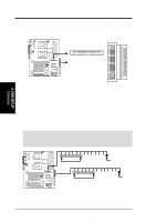
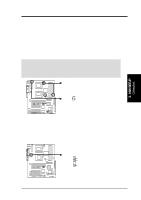
3. HARDWARE SETUP 6) Two 68-pin Ultra160/320 SCSI Connectors (SCSI-A, SCSI-B) This motherboard has two 68-Pin Ultra160/320 SCSI connectors; one for each of the two channels. Each channel can support a maximum of 15 devices as specified by Ultra160 standards. SCSI-A 68-Pin Ultra160/ 1 35 Ultra2-Wide SCSI Connector TR-DLS 34 1 68 35 SCSI-B 68-Pin Ultra160/ Ultra2-Wide SCSI Connector 3. H/W SETUP Connectors 34 68 TR-DLS Onboard SCSI Connectors SCSI Connection Notes This motherboard has two 68-Pin Ultra160 SCSI connectors; one for each of the two channels. The onboard SCSI chipset incorporates an advanced multimode I/O cell that supports both single-ended (SE), Ultra2, and Ultra160/320 devices. With Ultra160/320 devices, the SCSI bus platform performs at full Ultra160/320 speeds (up to 160MB/sec or 320MB/s) and extended cabling 12m (or 25m in a point-to-point configuration). When an SE device is attached, the bus defaults to an SE speed and 1.5m cable length. IMPORTANT: Connect SCSI devices as shown. Each channel should have only one type of SCSI standard (e.g. Ultra160/320, Ultra2, Ultra-Wide). Mixing SCSI devices on the same channel decreases performance of the slower device. 68-pin Internal SCSI Cable (Twisted-Pair Ribbon) Channel A TR-DLS 68-pin Female Internal SCSI Devices (up to 15 devices) Terminator 68-pin Internal SCSI Cable (Twisted-Pair Ribbon) Channel B Internal SCSI Devices (up to 15 devices) 68-pin Female Terminator TR-DLS SCSI Connection Example NOTE: Ultra160/320 SCSI devices do not have termination jumpers and must use a separate terminator on the last connector (internal) or device (external). 34 ASUS TR-DLS User's Manual
-
 1
1 -
2
-
3
-
4
-
5
-
6
-
7
-
8
-
9
-
10
-
11
-
12
-
13
-
14
-
15
-
16
-
17
-
18
-
19
-
20
-
21
-
22
-
23
-
24
-
25
-
26
-
27
-
28
-
 29
29 -
 30
30 -
 31
31 -
 32
32 -
 33
33 -
 34
34 -
 35
35 -
 36
36 -
 37
37 -
 38
38 -
 39
39 -
40
-
41
-
42
-
43
-
44
-
45
-
46
-
47
-
48
-
49
-
50
-
51
-
52
-
53
-
54
-
55
-
56
-
57
-
58
-
59
-
60
-
61
-
62
-
63
-
64
-
65
-
66
-
67
-
68
-
69
-
70
-
71
-
72
-
73
-
74
-
75
-
76
-
77
-
78
-
79
-
80
-
81
-
82
-
83
-
84
-
85
-
86
-
87
-
88
-
89
-
90
-
91
-
92
-
93
-
94
-
95
-
96
-
97
-
98
-
99
-
100
-
101
-
102
-
103
-
104
 |
 |
