Asus TS700-E4 User Manual - Page 40
Connect the IDE cable to the IDE, Connect a 4-pin plug from the, Push the optical drive all the way
 |
UPC - 610839645985
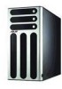
View all Asus TS700-E4 manuals
Add to My Manuals
Save this manual to your list of manuals |
Page 40 highlights
3. Move upward to release the bay lock. 4. Push the optical drive all the way to the depth of the bay. Make sure the screw holes on the optical drive match the ones on the chassis and the front edge of the optical drive align with the bay edge. 5. Slide the bay lock to the right until it clicks in place and secures the drive. 5. Connect the IDE cable to the IDE connector on the back of the drive. 6. Connect a 4-pin plug from the power supply to the power connector on the back of the drive. IDE cable 2-20 Power plug Chapter 2: Hardware setup
-
 1
1 -
2
-
3
-
4
-
5
-
6
-
7
-
8
-
9
-
10
-
11
-
12
-
13
-
14
-
15
-
16
-
17
-
18
-
19
-
20
-
21
-
22
-
23
-
24
-
25
-
26
-
27
-
28
-
29
-
30
-
31
-
32
-
33
-
34
-
 35
35 -
 36
36 -
 37
37 -
 38
38 -
 39
39 -
 40
40 -
 41
41 -
 42
42 -
 43
43 -
 44
44 -
 45
45 -
46
-
47
-
48
-
49
-
50
-
51
-
52
-
53
-
54
-
55
-
56
-
57
-
58
-
59
-
60
-
61
-
62
-
63
-
64
-
65
-
66
-
67
-
68
-
69
-
70
-
71
-
72
-
73
-
74
-
75
-
76
-
77
-
78
-
79
-
80
-
81
-
82
-
83
-
84
-
85
-
86
-
87
-
88
-
89
-
90
-
91
-
92
-
93
-
94
-
95
-
96
-
97
-
98
-
99
-
100
-
101
-
102
-
103
-
104
-
105
-
106
-
107
-
108
-
109
-
110
-
111
-
112
-
113
-
114
-
115
-
116
-
117
-
118
-
119
-
120
-
121
-
122
-
123
-
124
-
125
-
126
-
127
-
128
-
129
-
130
-
131
-
132
-
133
-
134
-
135
-
136
-
137
-
138
-
139
-
140
-
141
-
142
-
143
-
144
-
145
-
146
-
147
-
148
-
149
-
150
-
151
-
152
-
153
-
154
-
155
-
156
-
157
-
158
-
159
-
160
-
161
-
162
-
163
-
164
-
165
-
166
-
167
-
168
-
169
-
170
-
171
-
172
-
173
-
174
-
175
-
176
-
177
-
178
-
179
-
180
-
181
-
182
-
183
-
184
 |
 |

Chapter 2:
Hardware setup
2-20
5.
Connect the IDE cable to the IDE
connector on the back of the drive.
6.
Connect a 4-pin plug from the
power supply to the power
connector on the back of the drive.
3.
Move upward to release the bay
lock.
4.
Push the optical drive all the way
to the depth of the bay. Make sure
the screw holes on the optical drive
match the ones on the chassis and
the front edge of the optical drive
align with the bay edge.
5.
Slide the bay lock to the right until
it clicks in place and secures the
drive.
Power plug
IDE cable