Asus TS700-E4 User Manual - Page 48
SAS backplane connections
 |
UPC - 610839645985
View all Asus TS700-E4 manuals
Add to My Manuals
Save this manual to your list of manuals |
Page 48 highlights
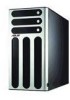
2.9.2 SAS backplane connections The SAS backplane has four 29-pin SAS connectors to support SAS hard disks. The backplane design incorporates a hot swap feature to allow easy connection or removal of SAS hard disks. The LEDs on the backplane connect to the front panel LEDs to indicate HDD access, HDD failure, thermal failure, or fan failure. See section "1.6 LED information." Front side The front side of the SAS backplane faces the front panel when installed. This side includes four SAS connectors for the hot swap drive trays. Disk drive 1 Disk drive 2 Disk drive 3 Disk drive 4 HDD status LEDs HDD activity LEDs Back side The back side of SAS backplane faces the rear panel when installed. This side includes the power connectors, SAS interfaces for the motherboard SAS connector or the SAS control card, an HDD fan connector, and SMBus connectors. 2-28 Chapter 2: Hardware setup
-
 1
1 -
2
-
3
-
4
-
5
-
6
-
7
-
8
-
9
-
10
-
11
-
12
-
13
-
14
-
15
-
16
-
17
-
18
-
19
-
20
-
21
-
22
-
23
-
24
-
25
-
26
-
27
-
28
-
29
-
30
-
31
-
32
-
33
-
34
-
35
-
36
-
37
-
38
-
39
-
40
-
41
-
42
-
 43
43 -
 44
44 -
 45
45 -
 46
46 -
 47
47 -
 48
48 -
 49
49 -
 50
50 -
 51
51 -
 52
52 -
 53
53 -
54
-
55
-
56
-
57
-
58
-
59
-
60
-
61
-
62
-
63
-
64
-
65
-
66
-
67
-
68
-
69
-
70
-
71
-
72
-
73
-
74
-
75
-
76
-
77
-
78
-
79
-
80
-
81
-
82
-
83
-
84
-
85
-
86
-
87
-
88
-
89
-
90
-
91
-
92
-
93
-
94
-
95
-
96
-
97
-
98
-
99
-
100
-
101
-
102
-
103
-
104
-
105
-
106
-
107
-
108
-
109
-
110
-
111
-
112
-
113
-
114
-
115
-
116
-
117
-
118
-
119
-
120
-
121
-
122
-
123
-
124
-
125
-
126
-
127
-
128
-
129
-
130
-
131
-
132
-
133
-
134
-
135
-
136
-
137
-
138
-
139
-
140
-
141
-
142
-
143
-
144
-
145
-
146
-
147
-
148
-
149
-
150
-
151
-
152
-
153
-
154
-
155
-
156
-
157
-
158
-
159
-
160
-
161
-
162
-
163
-
164
-
165
-
166
-
167
-
168
-
169
-
170
-
171
-
172
-
173
-
174
-
175
-
176
-
177
-
178
-
179
-
180
-
181
-
182
-
183
-
184
 |
 |
