Asus TUEP2-M TUEP2-M User Manual - Page 36
Internal Audio Connectors 4-pin CD1, AUX and MODEM
 |
View all Asus TUEP2-M manuals
Add to My Manuals
Save this manual to your list of manuals |
Page 36 highlights
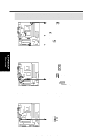
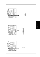
3. HARDWARE SETUP WARNING! Airflow across the CPU and onboard heatsinks is imperative, and the corresponding pins should be used accordingly. These are not jumpers, do not place jumper caps over these pins. CPU_FAN Rotation +12V GND ® TUEP2-M Rotation +12V GND PWR_FAN CHA_FAN Rotation +12V GND TUEP2-M 12-Volt Cooling Fan Power 5) Internal Audio Connectors (4-pin CD1, AUX and MODEM) These connectors allow you to receive stereo audio input from such sound sources as a CD-ROM, TV tuner, or MPEG card. The MODEM connector allows the onboard audio to interface with a voice modem card with a similar connector. Right Audio Channel Ground Left Audio Channel AUX (White) Modem-Out Ground Ground Modem-In MODEM ® TUEP2-M CD1 (Black) Left Audio Channel Ground Right Audio Channel TUEP2-M Internal Audio Connectors 6) Headphone True-Level Line Out Header (3-pin HEADPHONE) This connector allows you to connect chassis mounted headphone to the motherboard instead of having to attach an external headphone onto the ATX connectors. 3. H/W SETUP Connectors ® TUEP2-M HEADPHONE Headphone Right GND Headphone Left 1 TUEP2-M True-Level Line Out Header 36 ASUS TUEP2-M User's Manual
-
 1
1 -
2
-
3
-
4
-
5
-
6
-
7
-
8
-
9
-
10
-
11
-
12
-
13
-
14
-
15
-
16
-
17
-
18
-
19
-
20
-
21
-
22
-
23
-
24
-
25
-
26
-
27
-
28
-
29
-
30
-
 31
31 -
 32
32 -
 33
33 -
 34
34 -
 35
35 -
 36
36 -
 37
37 -
 38
38 -
 39
39 -
 40
40 -
 41
41 -
42
-
43
-
44
-
45
-
46
-
47
-
48
-
49
-
50
-
51
-
52
-
53
-
54
-
55
-
56
-
57
-
58
-
59
-
60
-
61
-
62
-
63
-
64
-
65
-
66
-
67
-
68
-
69
-
70
-
71
-
72
-
73
-
74
-
75
-
76
-
77
-
78
-
79
-
80
-
81
-
82
-
83
-
84
-
85
-
86
-
87
-
88
-
89
-
90
-
91
-
92
-
93
-
94
-
95
-
96
-
97
-
98
-
99
-
100
-
101
-
102
-
103
-
104
 |
 |
