Asus TUEP2-M TUEP2-M User Manual - Page 37
ASUS TUEP2-M User's Manual, Internal Microphone Connector 3-pin MIC2, ASUS iPanel Connector 24-1 pin
 |
View all Asus TUEP2-M manuals
Add to My Manuals
Save this manual to your list of manuals |
Page 37 highlights
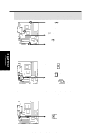
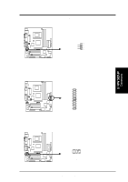
3. HARDWARE SETUP 7) Internal Microphone Connector (3-pin MIC2) This connector allows you to connect chassis mounted microphone to the motherboard. 3. H/W SETUP Connectors ® TUEP2-M MIC2 3 Ground MIC Input MIC Power 1 TUEP2-M Internal Microphone Connector 8) ASUS iPanel Connector (24-1 pin AFPANEL) This connector allows you to connect an optional ASUS iPanel, an easy to access drive bay with front I/O ports, status LEDs, and space reserved for a hard disk drive. ® TUEP2-M AFPANEL NC NC NC LOCKKEY SMBCLK +3VSB SMBDATA IRTX GND IRRX +5 V NC BATT PCIRST# MLED+5V EXTSMI# CHASSIS# +5VSB CIRRX NC GND NC TUEP2-M Front Panel Connectors 9) ASUS iPanel Audio Connector (10-1 pin AAPANEL) Connect the audio cable from the optional ASUS iPanel to this for front panel audio control. AAPANEL Line in_R AGND2 Line in_L AGND MIC2 Line out_R AGND3 Line out_L MICPWR ® TUEP2-M TUEP2-M Audio Panel Connectors ASUS TUEP2-M User's Manual 37
-
 1
1 -
2
-
3
-
4
-
5
-
6
-
7
-
8
-
9
-
10
-
11
-
12
-
13
-
14
-
15
-
16
-
17
-
18
-
19
-
20
-
21
-
22
-
23
-
24
-
25
-
26
-
27
-
28
-
29
-
30
-
31
-
 32
32 -
 33
33 -
 34
34 -
 35
35 -
 36
36 -
 37
37 -
 38
38 -
 39
39 -
 40
40 -
 41
41 -
 42
42 -
43
-
44
-
45
-
46
-
47
-
48
-
49
-
50
-
51
-
52
-
53
-
54
-
55
-
56
-
57
-
58
-
59
-
60
-
61
-
62
-
63
-
64
-
65
-
66
-
67
-
68
-
69
-
70
-
71
-
72
-
73
-
74
-
75
-
76
-
77
-
78
-
79
-
80
-
81
-
82
-
83
-
84
-
85
-
86
-
87
-
88
-
89
-
90
-
91
-
92
-
93
-
94
-
95
-
96
-
97
-
98
-
99
-
100
-
101
-
102
-
103
-
104
 |
 |
