Asus V2-AE1 User Guide - Page 13
Front panel
 |
View all Asus V2-AE1 manuals
Add to My Manuals
Save this manual to your list of manuals |
Page 13 highlights
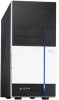
1.2 Front panel The front panel includes the optical drive bays, floppy disk drive slot, power button, and several I/O ports are located at the front panel. 1 2 3 6 4 5 7 8 1 . 5 . 2 5 - i n c h d r i v e b a y c o v e r. Covers two 5.25-inch bays for optical drives. 2 . 3 . 5 - i n c h d r i v e b a y c o v e r. Covers two 3.5-inch bays for a hard disk and a floppy disk drive. 3 . U S B 2 . 0 p o r t s. These Universal Serial Bus 2.0 (USB 2.0) ports are available for connecting USB 2.0 devices such as a mouse, printer, scanner, camera, PDA, and others. 4 . M i c r o p h o n e p o r t. This Mic (pink) +port connects a microphone. 5 . H e a d p h o n e p o r t. This Line In (green) port connects a headphone with a stereo mini-plug. 6. Hard disk drive activity LED. 7 . P o w e r b u t t o n. Press this button to turn the system on. 8 . R e s e t b u t t o n. Press this button to reboot the system without turning off the power. ASUS Vintage2-AE1 1-3
-
 1
1 -
2
-
3
-
4
-
5
-
6
-
7
-
 8
8 -
 9
9 -
 10
10 -
 11
11 -
 12
12 -
 13
13 -
 14
14 -
 15
15 -
 16
16 -
 17
17 -
 18
18 -
19
-
20
-
21
-
22
-
23
-
24
-
25
-
26
-
27
-
28
-
29
-
30
-
31
-
32
-
33
-
34
-
35
-
36
-
37
-
38
-
39
-
40
-
41
-
42
-
43
-
44
-
45
-
46
-
47
-
48
-
49
-
50
-
51
-
52
-
53
-
54
-
55
-
56
-
57
-
58
-
59
-
60
-
61
-
62
-
63
-
64
-
65
-
66
-
67
-
68
-
69
-
70
-
71
-
72
-
73
-
74
-
75
-
76
-
77
-
78
-
79
-
80
-
81
-
82
-
83
-
84
-
85
-
86
-
87
-
88
-
89
-
90
-
91
-
92
-
93
-
94
-
95
-
96
-
97
-
98
-
99
-
100
-
101
-
102
-
103
-
104
-
105
-
106
-
107
-
108
-
109
-
110
 |
 |
