Behringer ABACUS Quick Start Guide - Page 6
ABACUS Controls
 |
View all Behringer ABACUS manuals
Add to My Manuals
Save this manual to your list of manuals |
Page 6 highlights
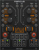
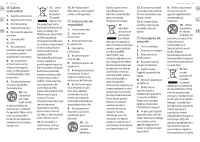
10 ABACUS ABACUS Controls (EN) Controls (1) CHANNEL 1 CV INPUT - Accepts variable voltages in the range +/- 10 V for processing by Channel 1. If no voltage is present the Abacus will use a self-generated voltage of approximately +10 V. (2) CHANNEL 1 TRIGGER INPUT - Accepts any positive-going gate or trigger above + 2.5 V. Causes the Rise/Fall function to be activated. (3) CHANNEL 2 CV INPUT - Accepts voltages in the range +/- 10 V for attenuverting by control 20. (4) CHANNEL 3 CV INPUT - Accepts voltages in the range +/- 10 V for attenuverting by control 21. (5) CHANNEL 4 TRIGGER INPUT - Accepts any positive-going gate or trigger above + 2.5 V. Causes the Rise/Fall function to be activated. (6) CHANNEL 4 CV INPUT - Accepts variable voltages in the range +/- 10 V for processing by Channel 4. If no voltage is present the Abacus will use a self-generated voltage of approximately +10 V. (7) CHANNEL 1 RISE CV INPUT - Allows CV control of the Rise function, in conjunction with control 8. Accepts voltages Quick Start Guide 11 in the range +/- 8 V. Positive voltages increase the Rise time until the maximum is achieved; negative voltages decrease it until it reaches minimum. (8) CHANNEL 1 RISE TIME - Use this control to set the Rise time. See table below for maximum times according to different settings. Can be modulated further by feeding a CV to socket 7. (9) CHANNEL 4 RISE TIME - Use this control to set the Rise time. See table below for maximum times according to different settings. Can be modulated further by feeding a CV to socket 10. (10) CHANNEL 4 RISE CV INPUT - Allows CV control of the Rise function, in conjunction with control 9. Accepts voltages in the range +/- 8 V. Positive voltages increase the Rise time until the maximum is achieved; negative voltages decrease it until it reaches minimum. (11) CHANNEL 1 BOTH CV INPUT - Accepts a voltage in the range +/- 8 V. A positive voltage will exponentially decrease the total Rise/Fall time, until the minimum is reached; a negative voltage exponentially increases it until it reaches maximum.
-
 1
1 -
 2
2 -
 3
3 -
 4
4 -
 5
5 -
 6
6 -
 7
7 -
 8
8 -
 9
9 -
 10
10 -
 11
11 -
 12
12 -
13
-
14
-
15
-
16
-
17
-
18
-
19
-
20
-
21
-
22
-
23
-
24
-
25
-
26
-
27
-
28
-
29
-
30
-
31
-
32
-
33
-
34
-
35
-
36
-
37
 |
 |
