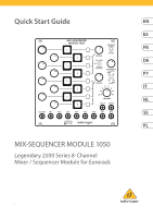
Behringer MIX-SEQUENCER MODULE 1050 Quick Start Guide - Page 6
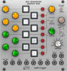
Ext Adv, In 1-8, Ext Gate Enable, Disable, Pulse Gen/off/manual, Advance, Pulse Rate, Counter/mixer
 |
View all Behringer MIX-SEQUENCER MODULE 1050 manuals
Add to My Manuals
Save this manual to your list of manuals |
Page 6 highlights
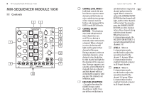
10 MIX-SEQUENCER MODULE 1050 (6) EXT ADV - Use this input to route in gate or clock signals to externally clock the rate at which the sequence advances. (7) IN 1-8 - Use these jacks to route audio signals into mixer Channels 1-8 via cables with 3.5 mm connectors. (8) EXT GATE (ENABLE/ DISABLE) - This two-way switch determines whether the sequencer is controlled via gate signals from the EXT GATE LINK 12-way connector located on the module underside. This 12-way connector allows compatible modules such as the CLOCKED SEQUENTIAL CONTROL MODULE 1027 to act as a master to the 1050 module. When DISABLE is selected the external gate signals will have no effect, when ENABLE is selected the 1050 module will follow the connected MASTER module. When using the EXT GATE input, the COUNTER switch would normally be set in the OFF position, however the module can be clocked from both the internal COUNTER and EXT GATE at the same time to produce random effects. If the underside EXT GATE LINK connector is not used, then the EXT GATE switch will have no effect on the 1050 module operation. (9) PULSE GEN/OFF/MANUAL ADVANCE - Use this three-way switch to determine whether the module advances through the channels in a sequence (PULSE GEN) or whether the module acts more like a standard mixer with manual channel selection (OFF). The OFF position would normally be selected when using the EXT ADVANCE jack or the underside module EXT GATE LINK connector. The MANUAL ADVANCE position, when selected, will advance the sequencer by one step. The ADVANCE switch position is momentary, so the switch will automatically return to the OFF position when released. (10) PULSE RATE - Use this knob to control the speed by which the internal pulse generator clocks and advances through each sequencer step. (11) COUNTER/MIXER - This three-way switch determines the sequence switching logic (COUNTER: two parallel rows of four versus a single sequence row of eight) and the audio routing logic (MIXER: two groups of four channels mixed to separate OUT A and OUT B outputs versus a single group of eight channels routed to both outputs). In the left position, the sequencer will count through the channels in two parallel rows of four, while the mixer outputs each row of four to separate outputs; In the far right position, the sequencer will count through all of the channels in a single sequence row of eight, while the mixer routes all eight channels as a single group to both outputs; the middle position is a mixed setting where the sequencer runs through the channels in two groups of four, but all eight audio channels are mixed and sent out as a single group. (12) COUNTER - Use this rotary switch to control the number Quick Start Guide 11 of steps in the sequence before the cycle repeats. When the COUNTER side of the COUNTER/MIXER switch is set for two sequences of four steps each, the COUNTER switch will only function up to the 4 setting. (13) EXT GATE LINK CONNECTOR - To connect the 1050 module to a 1027 module, insert the included 12-way cable into the EXT GATE LINK connector found on the 1050 module's underside, and then insert the other end of the cable into the 1027 module's EXT GATE LINK connector. The 1027 will now be the master and the 1050 will be the slave when the EXT GATE switch is set to ENABLE. (14) OUT A/B - Use these outputs to route the final mix out of the module for further processing elsewhere. When the COUNTER/MIXER switch is in the left position, the mixer will send the Channel 1 -4 group out through OUT A, while the Channel 5 -8 group goes out through OUT B. When the COUNTER/MIXER switch is in the center or
-
 1
1 -
 2
2 -
 3
3 -
 4
4 -
 5
5 -
 6
6 -
 7
7 -
 8
8 -
 9
9 -
 10
10 -
 11
11 -
 12
12 -
13
-
14
-
15
-
16
-
17
-
18
-
19
-
20
-
21
-
22
-
23
-
24
-
25
-
26
-
27
-
28
 |
 |
