Behringer ULTRAZONE ZMX8210 Manual - Page 8
Installation - audio mixer
 |
View all Behringer ULTRAZONE ZMX8210 manuals
Add to My Manuals
Save this manual to your list of manuals |
Page 8 highlights
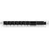
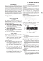
ULTRAZONE ZMX8210 Connect the potentiometer to pins V and SHD. Connect the mid tap to pin C (see Fig. 3.2). Volume potentiometer Fig. 3.2: Remote volume control connection with potentiometer Alternatively, you can control the volume by using a positive control voltage of max. 11 V DC. The voltage needs to be inserted between the pins SHD and C. ++ When using a voltage source to remote control the volume level, make sure that the control voltage does not exceed 11 V DC or else your unit could be damaged. Selecting stereo channels 7 and 8 To select the stereo channels 7 and 8, you need a push-button switch and optionally two LEDs. Connect the push-button switch to pins SHD and SEL. You can add two LEDs to indicate the selected channel. They have to be connected in parallel with a reverse polarity between the pins IND and SHD (see Fig. 3.3). 3.2 Basic operation Using the ZMX8210 is easy to learn and is very similar to using a standard mixer. Complete the following steps: 1) Hook up the unit as described in Chapter 3.1. 2) Adjust the LEFT, RIGHT and AUX LEVEL knobs [17] to center position and turn the LEVEL knobs {5} of each channel fully to the left. 3) Turn on the ZMX8210 and the other devices you want to use (amplifier and loudspeakers last). 4) Apply an audio signal (line or microphone signal) to an input channel. 5) Press the +48 V push-button switch {2} in case you want to use a capacitor microphone. 6) Press the push-button switches L, R and AUX {3} to select the buses to which the input signals are sent. 7) Turn the LEVEL knob of the corresponding channel to the right until == you have reached the required volume level == or the 0 db LED glows continuously. If the CLIP LED lights up, you need to adjust the level by slowly turning the knob to the left. For especially strong input signals, use the PAD push-button switch {1} to attenuate the signal further. 8) Repeat steps 4 to 7 with additional signal sources. Use channels 7 or 8 for stereo signal sources. 9) In case you are using a microphone, press the MIC LOW CUT push-button switch [11] to reduce low-frequency rumble such as subsonic noise. 10) Press the EQ ON push-button switch [14] and adjust the LOW, LOW MID, HIGH MID and HIGH knobs of the equalizer section (15) to modify the sound. 11) Use the LEVEL knobs of the LEFT, RIGHT and AUX buses [17] to adjust the volume level of the OUT L, OUT R and AUX outputs (zones). 4. Installation Control LED CH 8 4.1 Rack mounting The unit requires the height of 1 U to fit within a 19" rack. Please make sure to provide approximately 4" of space for the connectors on the rear panel. Please use M6 rack screws and nuts when rack-mounting the unit. 4.2 Audio connections The ZMX8210 connections are Euro-type connectors. You require special PCB connectors for the cabling. You can purchase the connectors at well-assorted electronics retailers. The ZMX8210 connectors' pin assignment is printed on the rear panel of the unit. Alternatively, refer to the following diagrams. INPUTS / AUX / OUT R / OUT L Channel select switch Control LED CH 7 Fig. 3.3: Connection with push-button switch and two LEDs for channel selection Fig. 4.1: Pin assignment of the INPUTS connectors 8 Installation
-
 1
1 -
2
-
 3
3 -
 4
4 -
 5
5 -
 6
6 -
 7
7 -
 8
8 -
 9
9 -
 10
10 -
 11
11 -
 12
12
 |
 |
