Biostar GF7050V-M7 Setup Manual - Page 15
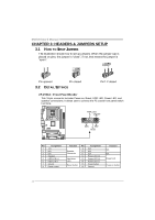
JATXPWR1: ATX Power Source Connector, JATXPWR2: ATX Power Source Connector
 |
View all Biostar GF7050V-M7 manuals
Add to My Manuals
Save this manual to your list of manuals |
Page 15 highlights
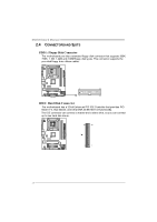
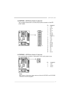
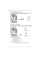
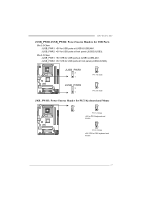
GF7050V-M7 JATXPWR1: ATX Powe r Source C onne ctor This connector allows user to connect 24-pin power connector on the ATX power supply. Pin Assignment 1 +3.3V 2 +3.3V 3 Ground 4 +5V 12 24 5 Ground 6 +5V 7 Ground 8 PW_OK 9 Standby Voltage +5V 10 +12V 11 +12V 12 +3.3V 13 +3.3V 14 -12V 15 Ground 16 PS_ON 17 Ground 1 13 18 Ground 19 Ground 20 -5V 21 +5V 22 +5V 23 +5V 24 Ground JATXPWR2: ATX Powe r Source C onne ctor By connecting this connector, it will provide +12V to CPU power circuit. 32 4 1 Pin Assignment 1 +12V 2 +12V 3 Ground 4 Ground Note: Befor e power on the s ystem, pleas e make sure that both J ATXPWR1 and JAT XPWR2 connectors have been pl ugged-in. 13
-
 1
1 -
2
-
3
-
4
-
5
-
6
-
7
-
8
-
9
-
 10
10 -
 11
11 -
 12
12 -
 13
13 -
 14
14 -
 15
15 -
 16
16 -
 17
17 -
 18
18 -
 19
19 -
 20
20 -
21
-
22
-
23
-
24
-
25
-
26
-
27
-
28
-
29
-
30
-
31
-
32
-
33
-
34
-
35
-
36
-
37
-
38
-
39
-
40
-
41
-
42
-
43
-
44
-
45
 |
 |
GF7050V-M7
13
JATXPWR1: ATX Power Source Connector
This connector allows user to connect 24-pin power connector on the ATX
power supply.
Pin
Assignment
1
+3.3V
2
+3.3V
3
Ground
4
+5V
5
Ground
6
+5V
7
Ground
8
PW_OK
9
Standby
Voltage +5V
10
+12V
11
+12V
12
+3.3V
13
+3.3V
14
-12V
15
Ground
16
PS_ON
17
Ground
18
Ground
19
Ground
20
-5V
21
+5V
22
+5V
23
+5V
1
12
13
24
24
Ground
JATXPWR2: ATX Power Source Connector
By connecting this connector, it will provide +12V to CPU power circuit.
Pin
Assignment
1
+12V
2
+12V
3
Ground
1
2
3
4
4
Ground
Note:
Befor e power on t he s yst em, pleas e make sure that bot h J ATXPWR1 and JAT XPWR2
connectors have been pl ugged-in.