Biostar GF7050V-M7 Setup Manual - Page 17
JSPDIF_O UT1: Digital Audio out Connectors, JAUDIOF1: Front Panel Audio Header
 |
View all Biostar GF7050V-M7 manuals
Add to My Manuals
Save this manual to your list of manuals |
Page 17 highlights
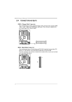
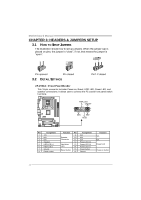
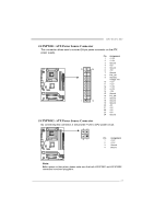
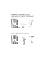
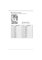
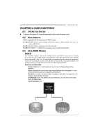
GF7050V-M7 JSPDIF_O UT1: Digital Audio out Conne ctors This connector allows user to connect the PCI bracket SPDIF output header. Pin Assignment 1 +5V 2 SPDIF_OUT 1 3 Ground 3 1 JAUDIO F1: Front Panel Audio Heade r This header allows user to connect the front audio output cable with the PC f ront panel. This header allows only HD audio front panel connector; AC'97 connector is not acceptable. 2 10 1 9 Pin Assignment 1 Mic Left in 2 Ground 3 Mic Right in 4 GPIO 5 Right line in 6 Jack Sense 7 Front Sense 8 Key 9 Left line in 10 Jack Sense 15
-
 1
1 -
2
-
3
-
4
-
5
-
6
-
7
-
8
-
9
-
10
-
11
-
 12
12 -
 13
13 -
 14
14 -
 15
15 -
 16
16 -
 17
17 -
 18
18 -
 19
19 -
 20
20 -
 21
21 -
 22
22 -
23
-
24
-
25
-
26
-
27
-
28
-
29
-
30
-
31
-
32
-
33
-
34
-
35
-
36
-
37
-
38
-
39
-
40
-
41
-
42
-
43
-
44
-
45
 |
 |
GF7050V-M7
15
JSPDIF_O UT1: Digital Audio out Connectors
This connector allows user to connect the PCI bracket SPDIF output header.
Pin
Assignment
1
+5V
2
SPDIF_OUT1
1
3
3
Ground
JAUDIOF1: Front Panel Audio Header
This header allows user to connect the front audio output cable with the PC front
panel. This header allows only HD audio front panel connector; AC’97 connector
is not acceptable.
Pin
Assignment
1
Mic Left in
2
Ground
3
Mic Right in
4
GPIO
5
Right line in
6
Jack Sense
7
Front Sense
8
Key
9
Left line in
10
Jack Sense
1
9
2
10